- Catalogs
- Watts Water Technologies
- 10 gpm Commercial RO w/ Adjustable Recovery
10 gpm Commercial RO w/ Adjustable Recovery

10 gpm Commercial RO w/ Adjustable Recovery
- Ensure water is microbiologically safe before use.
- Turn off the unit, shut off feed water, and disconnect power during servicing.
- Avoid running the pump dry or starting with the reject valve closed.
- Prevent freezing and operation above 100°F.
- Models: R24-08, R24-10, R24-12
- Maximum Productivity: 14,400 to 21,600 gallons per day
- Typical Membrane Rejection: 98%
- Recovery Rates: 59% to 75%
- Membrane Size: 4 x 40 inches
- Electrical Requirement: 230 VAC, 3-ph, 60 Hz, 15 amps
- Controller: Manages system operation and displays water quality.
- Reject Control Valve: Manages reject flow.
- Pump Discharge Valve: Throttles the pump.
- Gauges and Meters: Monitor pressures and flow rates.
- Ensure water supply pressure is at least 20 psig.
- Install proper pretreatment before the RO system.
- Install indoors with space for membrane removal.
- Connect pretreated feed water to the prefilter housing.
- Ensure product and reject water lines are unrestricted.
- Install a safety switch or fused disconnect within 10 feet.
- Verify disconnect switch is de-energized before connecting.
- Verify pretreatment equipment is operational and chlorine-free.
- Open necessary valves and purge air from the system.
- Adjust valves to achieve desired flow rates.
Catalog excerpts
REVERSE OSMOSIS INSTALLATION AND OPERATION MANUAL R24-SERIES >
Open the catalog to page 1
IMPORTANT Do not use where the water is microbiologically unsafe. Always turn off the unit, shut off the feed water, and disconnect the electrical power when working on the unit. Never allow the pump to run dry. Never start the pump with the reject valve closed. Please read the entire manual before proceeding with the installation and startup: Never allow the unit to freeze or operate with a feed water temperature above 100 F. NOTES Changes in operating variables are beyond the control Alamo Water Refiners, Inc. The end user is responsible for the safe operation of this equipment. The suitability...
Open the catalog to page 2
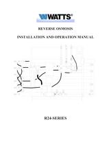
TABLE OF CONTENTS I. Introduction A. Specifications B. Overview C. Pre-treatment II. Controls, Indicators, and Components A. Figure # 1 General System Drawing B. Figure # 2 Controller Option One C. Figure # 3 Controller Option Two III. Operation A. Installation B. Plumbing Connections C. Electrical Connections D. Startup E. Controllers F. Operation and Maintenance Log G. Trouble Shooting IV. Replacement Parts List V. Membrane Replacement VI. Appendix Flow Rate Guidelines Temperature Correction Factors Electrical Schematics Grundfos Pump Filmtec Technical Information - Cleaning and Disinfection...
Open the catalog to page 3
Internal flows across the membrane surface must be high enough to prevent settling of fine suspended solids on the membrane surface. I. INTRODUCTION The separation of dissolved solids and water using RO membranes is a pressure driven temperature dependent process. The membrane material is designed to be as permeable to water as possible while maintaining the ability to reject dissolved solids. The main system design parameters require the following: The concentration of each dissolved ionic species must not exceed the limits of solubility anywhere in the system. Pre-treatment must be sufficient...
Open the catalog to page 4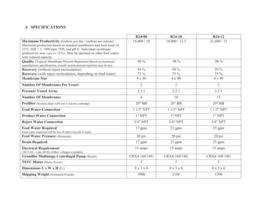
R24-08 R24-10 R24-12 Maximum Productivity > (Gallons per day / Gallons per minute) Maximum production based on standard membranes and feed water of 25C, SDI < 3, 1000 ppm TDS, and pH 8. Individual membrane productivity may vary (б 15%). May be operated on other feed waters with reduced capacity. 14,400 / 10 18,000 / 12.5 21,600 / 15 Quality > (Typical Membrane Percent Rejection) Based on membrane manufactures specifications, overall system percent rejection may be less. 98 % 98 % 98 % Recovery (without reject recirculation) Recovery (with reject recirculation, depending on feed water) 59 % 75...
Open the catalog to page 5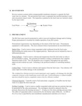
C. PRETREATMENT The RO feed water must be pretreated in order to prevent membrane damage and/or fouling. Proper pretreatment is essential for reliable operation of any RO system. Pretreatment requirements vary depending on the nature of the feed water. Pretreatment equipment is sold seperatly. The most common forms of pretreatment are described below. Media Filter B. RO OVERVIEW Reverse osmosis systems utilize semipermeable membrane elements to separate the feed water into two streams. The pressurized feed water is separated into purified (product) water and concentrate (reject) water. The impurities...
Open the catalog to page 6
recommended. Iron & Manganese - These foulants should be removed to less than 0.1 ppm. Special media filters and/or chemical treatment is commonly used. pH - The pH is often lowered to reduce the scaling potential. Silica : Reported on the analysis as SiO2. Silica forms a coating on membrane surfaces when the concentration exceeds its solubility. Additionally, the solubility is highly pH and temperature dependent. Silica fouling can be prevented with chemical injection and/or reducing the recovery. II. CONTROLS, INDICATORS, and COMPONENTS (see figure 1) B. Reject Control Valve - Controls the...
Open the catalog to page 7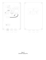
Figure 2 Controller Package One >
Open the catalog to page 9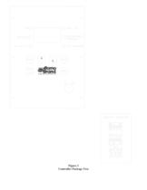
Figure 3 Controller Package Two >
Open the catalog to page 10
III. OPERATION A. INSTALLATION 1. The water supply should be sufficient to provide a minimum of 20 psig pressure at the design feed flow. 2. Proper pretreatment must be determined and installed prior to the RO system. 3. A fused high voltage disconnect switch located within 10 feet of the unit is recommended. This disconnect is not provided with the RO system. 4. Responsibility for meeting local electrical and plumbing codes lies with the owner / operator. 5. Install indoors in an area protected from freezing. Space allowances for the removal of the membranes from the pressure vessels should...
Open the catalog to page 11
4. Do not apply power to the RO unit at this time. D. STARTUP 1. Verify that the pretreatment equipment is installed and working properly. Verify that no free chlorine is present in the feed water. 2. Verify that the on/off switch is in the off position. 3. Verify that the pump discharge valve (Figure # 1 item C) is open. 4. Install a 20" five micron filter cartridge in the prefilter housing. (Figure #1 item I) 5. Open the reject control valve completely (Figure # 1 item B) by turning it counterclockwise. Close the reject recycle control valve completely if the reject recycle option is included....
Open the catalog to page 12
Two controller options are available. Controller option # 1 is a basic controller with an on / off switch, low pressure, tank level, and pretreatment interlock (see figure # 2). Automatic low pressure reset If the unit shuts down due to low pressure, a red light on the front of the controller will illuminate. The controller will automatically restart the unit after a user selected time delay. The user selects the delay time by positioning a jumper cap inside the controller (see attached drawing). Tank Level / Pretreatment Indicator If the unit shuts down due to a high product tank level or pretreatment...
Open the catalog to page 13
Controller option # 2 is the CI 1000. This is a microprocessor based controller with a product water conductivity meter. A separate manual for this controller begins on the next page. The autoflush option is available with both controllers. On controllers # 1, the flush valve is preset to open for 2 minutes every time the pump starts and 2 minutes every hour. On controller #2, the flush times are user programmable. (See the following CI1000 information.) >
Open the catalog to page 14All Watts Water Technologies catalogs and technical brochures
 Backflow Prevention
92 Pages
 Hydronic Heating Specialties
60 Pages
 WATTS.COM/CAD
1 Page
 Watts Flow Switch
2 Pages
 Thermostatic Mixing Valves
12 Pages
 Watts PRV Irrigation
1 Page
 Thermal Expansion Products
24 Pages
 Water Pressure Reducing Valves
44 Pages
 Flippen Float Valves
12 Pages
 Ball Valves
28 Pages
 Steam Pressure Regulators
8 Pages
 Solar Solutions
20 Pages
 OneFlow Model OFTWH
2 Pages
 LavSafe Thermostatic Faucets
4 Pages
 Series X65B
2 Pages
 OneFlow® Anti-Scale Systems
2 Pages
 Watts Boiler Header Module
4 Pages
 Steam Products
24 Pages
 008 PCQT
2 Pages
 Series 17
1 Page
 Series 152SS
2 Pages
 Series 152A
2 Pages
 Series 150A
2 Pages
 Series 1450F
1 Page
 Series 144
2 Pages
 Series 142
2 Pages
 Series 40, 140, 240 & 340
2 Pages
 Model 127W
2 Pages
 ES-127
2 Pages
 Series 123LP
1 Page
 Series 1170 and L1170
2 Pages
 Series 1156F
2 Pages
 Series 1L, 1XL, 10L
2 Pages
 Series 100DT
1 Page
 Series 05
2 Pages
 Series 007
4 Pages
 Flow-Max Filters
4 Pages
 Bottom-Entry Pressure Gauges
2 Pages
 Flanged Gate Valves
2 Pages
 Brass Midi Check Valves
2 Pages
 Wafer Style Butterfly
2 Pages
 carbon steel ball valve
2 Pages


- Liebherr piping
- Liebherr connector
- Liebherr fitting
- Liebherr manual valve
- Liebherr flow meter
- Liebherr stainless steel valve
- Liebherr hydraulic fitting
- Liebherr water valve
- Liebherr screw-in fitting
- Liebherr ball valve
- Volume flow monitor
- Liquid flow monitor
- Liebherr pneumatic fitting
- Liebherr metal fitting
- Liebherr regulating valve
- Liebherr liquid filter
- Liebherr electrical power supply connector
- Liebherr flange valve