- Catalogs
- WARNER ELECTRIC
- General Catalog
General Catalog
1 /956Pages

General Catalog
1 /956Pages
Catalog excerpts

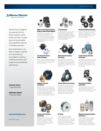
Custom Design Clutches and Brakes Product Line Clutches SF series Clutch Couplings Page 14 Stationary Field Design Page 90 Stationary Field Design Flange or bearing mounted styles The SFC Series clutch couplings employ the same basic components as the SF design except for a splined hub and adapter which serves as a coupling for in-line shaft applications. The SF design eliminates collector rings and brushholder. Ideal for adverse environmental conditions. Mounting tolerances are generally more critical than the PC design. PC series SFC series Page 72 Primary Design Current is carried through...
Open the catalog to page 2
Custom Design Clutches and Brakes Product Line Brakes Clutch/Brake Combinations PB series Page 146 Brake The PB Series brakes consist of a magnet, armature and mounting hub in a very simple and extremely compact design. Page 188 The PCB Series clutch-brakes combine a PC clutch and a PB brake into one compact design. Application Application A clutch-brake is used to combine the functions of a clutch and a brake in a compact assembly. A brake is used when a rotating load is to be stopped. MB series PCB series Primary style clutch/brake Page 176 Motor Brake MB motor brakes are composed of a PB Series...
Open the catalog to page 3
Custom Design Clutches and Brakes Design Features Versatility and Flexibility Coil Available in various voltages for each model. Warner Electric controls (see controls section) provide optimum performance and controllability. All Warner Electric units are either UL listed or recognized. All are CSA certified. Armature Fluted and segmented. Designed as a cooling device to dissipate maximum heat and increase life. Magnet or Field Brake magnet mounts to any machine member. Warner Electric clutches are available in flange mount or bearing mount designs. Bushings Standard industry bushings are used...
Open the catalog to page 4
Custom Design Clutches and Brakes Design Features Two clutch designs Antibacklash Armature Autogap™ System • Positive Disengagement The Autogap is a system designed to separate the armature from the friction face. This spacing is automatic and occurs prior to total magnetic decay, effectively eliminating noise by preventing drag. The leaf springs which attach armature to hub pull the armature back sharply when the coil is deenergized, providing positive disengagement. Wear, heat, and noise caused by dragging armatures are eliminated. • Bi-Directional Operation SF design Stationary Field Clutches...
Open the catalog to page 5
Custom Design Clutches and Brakes Outside Overall Model Max. Rated Diameter Length Number Torque (inches) (inches) Page No. Outside Overall Model Max. Rated Diameter Length Number Torque (inches) (inches) Page No. Outside Overall Model Max. Rated Diameter Length Number Torque (inches) (inches) Page No. Outside Overall Model Max. Rated Diameter Length Number Torque (inches) (inches) Page No.
Open the catalog to page 6
Custom Design Clutches and Brakes Outside Overall Model Max. Rated Diameter Length Number Torque (inches) (inches) Page No. Model Max. Rated Diameter Number Torque (inches) Outside Overall Max. Rated Diameter Length Torque (inches) (inches) Model Max. Rated Diameter Number Torque (inches) Outside Overall Max. Rated Diameter Length Torque (inches) (inches) Page No.
Open the catalog to page 7
Custom Design Clutches and Brakes Selection Clutch Selection Determine the shaft speed at the clutch location. The number listed at the intersection of the horsepower and speed lines is the size unit you require. EXAMPLE: START APPLICATION Function: To couple the output shaft of a motor in line with the input shaft of a reducer. Clutch – Horsepower vs. Shaft Speed HP SHAFT SPEED AT CLUTCH (IN RPM) 100 200 300 400 500 600 700 800 900 1000 1100 1200 1500 1800 2000 2400 3000 3600 4000 4600 5000 1/50 170 1/20 1/12 1/8 250 1/6 1/4 Type: A clutch coupling will couple two in line shafts. 1/3 Size: The...
Open the catalog to page 8
Custom Design Clutches and Brakes Selection Brake Selection Determine the shaft speed at the brake location. The number listed at the intersection of the horsepower and speed lines is the size unit you require. MOTOR BRAKE Frame Sizes are listed on product specification sheets. Brake – Horsepower vs. Shaft Speed HP SHAFT SPEED AT BRAKE (IN RPM) 100 200 300 400 500 600 700 800 900 1000 1100 1200 1500 1800 2000 2400 3000 3600 4000 4600 5000 1/50 1/20 170 1/12 EXAMPLES: STOP APPLICATION 1/8 Function: To stop a lathe spindle. 1/4 Type: A brake will provide either a rapid or cushioned stop. 1/3 Size:...
Open the catalog to page 9
Custom Design Clutches and Brakes Selection Torque Calculations Based on Motor HP of Drive Based on Load Inertia and Time The formula to use when calculating clutch torque requirement based on motor HP is: Tav = WR2N 308t 5,250 x HP x 2.75* T = ––––––––––––––––– N Where: WR2 = inertial load in terms of lb.ft.2 referred to at the unit location. N = RPM Where: HP = name plate HP of the motor *K = motor overload factor = 2.75 t = time allowed for the engagement Tav = Average Torque (lb.ft.) This formula gives us the torque (T) and is the average amount of torque required to accelerate a part from...
Open the catalog to page 10
Custom Design Clutches and Brakes Selection Torque and Horsepower Relationship Example: Find Tc: When selecting clutches and brakes Warner Electric disregards efficiency or frictional losses in pulley, sprocket or gearing drive trains. Torque on a clutch or brake will be greater or lesser than the torque at the motor shaft based on the speed differences between the motor shaft and the shaft where the clutch or brake is located. This is an inverse 1:1 relationship. A clutch at the slow speed side of a 10:1 ratio speed reduction will need to accelerate 10 times the torque as a clutch at the motor...
Open the catalog to page 11
Custom Design Clutches and Brakes Mounting Examples and Options Warner Electric custom design brakes and clutches are economical to purchase and simple to install. They consist of components which must be assembled on the shaft and properly attached to the machine frame. Various customer furnished drive components must be assembled with the brake or clutch. Pulleys, sprockets and bearings/pillow blocks for shafting may be essential elements of a complete drive system. Squareness and concentricity tolerances are specified where critical to proper clutch/brake functioning. SF Clutches and SFC Clutch...
Open the catalog to page 12All WARNER ELECTRIC catalogs and technical brochures
 Multi Disc Torque Limiters
8 Pages
 Literature/line-cards
2 Pages
 Clutches and Brakes
92 Pages
 Tension Control Systems
80 Pages
 Sensors and Switches
68 Pages
 Fractional HP Clutches/Brakes
20 Pages
 UNIBRAKE ® AC Motor Brakes
20 Pages
 Shaft Mounted Clutches & Brakes
112 Pages
 ERS VAR-11-01
2 Pages
 P310 VAR 00/VAR 10
92 Pages
 CMS 250 Product Brochure
4 Pages
 WSC Series
6 Pages
 Super CB Series
7 Pages
 Electro Clutches (EC)
7 Pages
 UM Series
10 Pages
 EUM Series
10 Pages
 UM Smooth-Start
2 Pages
 UM-C Series
7 Pages
 UM-W Series
8 Pages
 EM series
16 Pages
 EB series
6 Pages
 EC series
7 Pages
 MTB series
10 Pages
 ATT series
6 Pages
 TB series
4 Pages
 CB series
9 Pages
 Clutch/Brake Controls
1 Page


Archived catalogs
 MagStop Clutch/Brake
2 Pages
 Mistral series
4 Pages
 Limit Switches
8 Pages
 general catalog 2007
956 Pages

- Round plug
- Technology switch
- Friction brake
- Safety electric switch
- Male plug
- Metal plug
- Disc brake
- Spring brake
- Friction brake caliper
- Electromagnetic brake
- Touch switch
- Friction clutch
- Disc brake caliper
- Overload clutch
- Industrial switch
- Electromagnetic clutch
- Hydraulic brake
- Multi-axis positioning controller
- Control switch
- Pneumatic brake