

Installation manual EcoPro
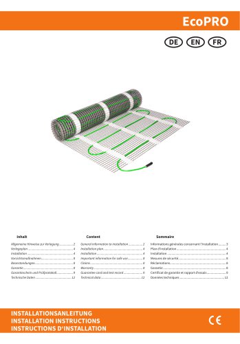
Installation manual EcoPro
The document provides comprehensive instructions for installing EcoPRO heating mats. Key points include ensuring the heating mat is not operated while coiled, adjusting only the cold lead wires, and not directly connecting heating wires to the power supply. A minimum contact opening of 3 mm is required for disconnection, and mats should be wired in parallel. The protective braiding must be connected to the grounding system, and installations in bathrooms must comply with VDE 0100 regulations.
A layout plan should be created before installation, noting non-heating zones near walls. The heating mat must maintain a minimum distance of 30 mm from conductive building parts.
Installation must be performed by a qualified electrician according to DIN-VDE standards. The heating mat should be connected to a 230 VAC power supply through a junction box, ensuring the total current does not exceed the thermostat's capacity. Heating cables must not be crossed or bent sharply, and a ground fault circuit breaker is mandatory. The installation temperature should be at least +5°C, and the mat should not be installed under furniture or through insulation materials.
The subfloor must be even, secure, and clean. If uneven, it should be leveled with a suitable compound. Heating cables must be fully embedded in leveling compound or tile adhesive, and the system should not be activated until all materials have fully cured. Only certified materials should be used for installation.
The manufacturer guarantees defect-free materials, but damages due to improper handling or installation are not covered.
The maximum operating temperature for the heating mat is 80°C.
The subfloor must be even, secure, solid, and capable of bearing the load. It should be clean, dry, and free from dust and sharp objects. A self-leveling floor compound should be used if uneven, and installation must not bridge expansion joints in the building structure.
Channels for power supply wires, cold leads, and temperature sensors must be chiseled out in the wall and floor. Cold leads and sensor cables should be installed in separate corrugation tubes. A standard plastic recessed electrical box with a 230 VAC power supply is required for the thermostat installation, and a ground fault circuit breaker (30 mA) must be provided.
The heating mat should be fixed to the subfloor with the adhesive side down, following the layout plan. The glass fiber mesh can be cut at turning points, but care must be taken not to damage the heating cable. A safety distance of 4-6 cm between mat turnings must be maintained, with a minimum distance of 3 cm. Soft-soled shoes should be worn during installation to prevent damage.
For PVC and carpet floor finishings, the heating mat must be covered with 5-10 mm of leveling material. The thermal conductivity of the surface covering must be appropriate, and insulation values should not exceed specified limits. The heating mat should be secured with dowels to prevent movement when using leveling screed.
The sensor cable must be placed in a separate conduit according to EN 61386-1, positioned centrally between two heating conductors. The cold lead should be routed through a separate tube to the electrical box, maintaining a minimum distance of 2 cm from the heating wires. Ensure the sensor can be easily removed from the conduit before installing the screed and floor covering.
During the application of tile adhesive or spattling compound, care must be taken not to damage the heating conductor insulation. The heating wire must be fully covered. After laying the floor finish, measure and record the heating section and insulation resistance. Expansion joints should be grouted with silicone, and the product identification label should be placed at the electrical box.
The temperature sensor cable must be placed in a separate corrugated tube according to NF EN 61386-1 standards. The soil sensor should be positioned directly under the heating mat, centered between two heating conductors, and at least 2 cm away from them. The connection cable of the mat should run parallel to the standard plastic recessed box without crossing the heating conductor. A 230 V AC power supply and a 30 mA residual current circuit breaker are required for the electronic thermostat installation.
Ensure the sensor can be inserted and removed from the corrugated tube (Ø16mm) during installation and before laying the screed or floor covering. The electrical connection must be performed by a qualified electrician, adhering to national laws and regulations. Disconnect the local power supply before installing or checking the thermostat.
Different floor finishes have varying thermal resistances, such as tile (0.012 m²K/W), carpet (0.09 m²K/W), PVC (0.01 m²K/W), cork (0.13 m²K/W), and parquet (0.11 m²K/W).
Only plastic recessed boxes should be used for thermostat installation. The installation instructions and wiring diagram do not replace professional expertise. Ensure the sensor can be removed from the corrugated tube during and after installation.
The manufacturer guarantees the heating mat's conformity with the design description, assuming compliance with installation and operating instructions. The warranty period is two years from the purchase date. It covers manufacturing defects but excludes damages from improper handling or incorrect installation.
The EcoPRO heating mat consists of a screened series resistance heating cable on a fiberglass mesh, with a constant cable-to-cable distance. It includes a metallic sheath for mechanical strength and safety. The mat is available in various power ratings, such as EcoPRO-150-1.0/150 with 150 W/m² and EcoPRO-100-1.0/100 with 100 W/m².
The document provides detailed specifications for various EcoPRO models with different power densities: 100 W/m², 200 W/m², and 160 W/m². Each model is listed with parameters such as length (m), width (m), area (m²), power (W), resistance at +20°C (Ω), tolerance range (-5%, +10%), and current (A).
Models range from EcoPRO-200-2.0/100 to EcoPRO-1500-15.0/100, with power outputs from 200 W to 1500 W. Resistance values decrease as power increases, indicating higher efficiency in larger models.
Models range from EcoPRO-200-1.0/200 to EcoPRO-3000-15.0/200, with power outputs from 200 W to 3000 W. These models offer higher power density, suitable for applications requiring more heat output per unit area.
Models range from EcoPRO-160-1.0/160 to EcoPRO-2400-15.0/160, with power outputs from 160 W to 2400 W. These models provide a balance between power output and efficiency.
The document includes a disclaimer stating that all information is believed to be reliable and correct to the best of the company's knowledge. It notes that modifications, mistakes, and printing errors do not justify claims for compensation, and liability is governed by the general terms and conditions. Specifications are subject to change without prior notice.
Catalog excerpts
INSTALLATIONSANLEITUNG INSTALLATION INSTRUCTIONS INSTRUCTIONS D
Open the catalog to page 1
ALLGEMEINE HINWEISE ZUR VERLEGUNG • Die Heizmatte niemals in aufgerolltem Zustand in Betrieb nehmen oder an das Netz anschließen. • Bei der Verlegung dürfen nur die Kaltleiteranschlussleitungen gekürzt oder verlängert werden. • Die Heizleitungen selbst dürfen weder direkt an das Netz angeschlossen noch gekürzt werden. • In der Zuleitung ist eine Sicherung mit einer Kontaktöffnung von mind. 3 mm zu installieren. • Die Heizmatte immer nur parallel und nicht in Reihe verdrahten. • Die Schutzumflechtung der Anschlussleitung ist an die Erdungsmaßnahme (PE-Leiter) anzuschließen. • Die Installation...
Open the catalog to page 2
• The minimum distance of the heating mat to the wall or to ascending components (e.g. bathtubs, shower trays) must be 5 cm. The distance to conductive building parts (e.g. hot water pipes) must be at least 3 cm. In order to remain flexible in the positioning of the furniture, or in cases where the final position of the furniture is not yet known (especially in rental apartments and houses), a distance of 60 cm to the partition wall should be kept free. • Before and after the installation, always measure and record the total resistance of the heating mat and the insulation resistance. • Always...
Open the catalog to page 3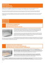
VERLEGEPLAN INSTALLATION PLAN PLAN L‘INSTALLATION Erstellen Sie sich einen Verlegeplan für die Heizmatte und notieren Sie sich die heizungsfreien Zonen an den raumumschließenden Wänden. Die Heizmatte muss mindestens einen Abstand von 30 mm zu leitfähigen Teilen des Gebäudes haben (z.B. Wasserleitungen). Draw the layout of the electrical underfloor heating mat and write down the zones free of the heating mat and spacings at the surrounding walls. The distance of the electrical heating mat and any conductive parts of the building have to be at a minimum of 30 mm (for example, water pipe). Dessinez...
Open the catalog to page 4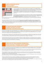
EINSCHNEIDEN UND DREHEN MAT ADJUSTMENT AJUSTEMENT DE LA NATTE Fixieren Sie die Elektro-Comfort-Dünnbettheizung gemäß Ihrem Verlegeplan mit der Klebeseite auf dem Untergrund. Schneiden Sie an der vorgesehenen Wendestelle das Glasfasergewebe ein (Achtung! Heizleitung nicht beschädigen!) und verlegen Sie die Heizmatte, wie in der Illustration dargestellt. Nachdem die geplante Form der Verlegung erreicht ist, drücken Sie die Elektro-Comfort-Dünnbettheizung fest auf den Untergrund. Das Trägergewebe muss faltenfrei auf dem Boden verlegt werden! Bei Verwendung von Fließestrich sollte die Heizmatte mit...
Open the catalog to page 5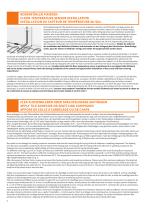
BODENFÜHLER FIXIEREN FLOOR TEMPERATURE SENSOR INSTALLATION INSTALLATION DU CAPTEUR DE TEMPÉRATURE AU SOL Die Fühlerleitung des Thermostats muss in einem separaten Leerrohr nach EN 61386-1 verlegt werden. Der Bodenfühler muss unmittelbar unter der Heizmatte positioniert werden, indem ein Schlitz im Boden aufgestemmt und das Leerrohr darin versenkt wird. Der Fühler sollte mittig zwischen zwei Heizleitern positioniert werden, also in der Mitte einer Heizkabelschlaufe. Verlegen Sie den Kaltleiter (Netzanschlussleitung) in einem separaten Leerrohr seitlich bis zur Anschlussdose und kreuzen Sie hierbei...
Open the catalog to page 6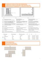
THERMOSTAT-INSTALLATION UND BODENAUFBAU THERMOSTAT INSTALLATION AND FLOOR CONSTRUCTION INSTALLATION DU THERMOSTAT ET CONSTRUCTION DU SOL 1 1 Elektronisches Thermostat; Zuleitung NYM 3 x 1,5 mm² zur Verteilung Electrical thermostat; Power supply distribution cable NYM 3 x 1,5 mm² Thermostat électronique; Câble d‘alimentation NYM 3 x 1,5 mm² pour la répartition Wellrohr für Temperaturfühler (Bodenfühler) oder Kaltleiter (beide dürfen nicht zusammen in einem Rohr verlegt werden) Corrugated tube for the temperature sensor or the cold lead (both are not to be installed inside the same tube) Tube ondulé...
Open the catalog to page 7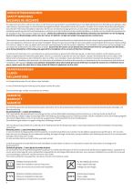
VORSICHTSMASSNAHMEN SAFETY WARNINGS MESURES DE SÉCURITÉ Der elektrische Anschluss und der Anschluss an die Stromversorgung dürfen ausschließlich durch eine Elektrofachkraft unter Einhaltung der gültigen nationalen Gesetze, Bestimmungen und Vorschriften durchgeführt werden. Andernfalls erlischt die Garantie. Schalten Sie Ihr lokales Stromnetz spannungsfrei, bevor Sie den Thermostat installieren oder bevor Sie ihn von der Stromversorgung trennen, um das Gerät zu überprüfen oder um es auszutauschen. Die Installationsanleitung und das Anschlussdiagramm ersetzen nicht die Fachkenntnisse des Geräteinstallateurs....
Open the catalog to page 8
Ausgefulltes Prufprotokoll/Garantieschein sind Grundlage fur Garantieanspruch. The completed resistance acceptance test certificate/guarantee card are necessary for warranty claims. Le rapport d'essais/ certificat de garantie remplis sont necessaire pour les reclamations sous garantie. Heizmatten-Typ / Heating mat type / Type de natte chauffante :
Open the catalog to page 9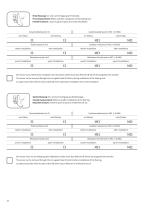
Erste Messung: Vor und nach Verlegung der Heizmatte. First measurement: Before and after installation of the heating mat. Première mesure : Avant et après la pose de la natte chauffante. Isolationswiderstand in MW (>10 MW) nach Einbau Total resistance in W before installation Isolation resistance in MW (>10 MW) after installation before installation Résistance totale en W avant l‘installation nach Einbau after installation après l‘installation avant l‘installation après l‘installation Der Sensor kann während der Installation der Heizmatte wieder durch das Wellrohr (Ø 16mm) herausgenommen werden....
Open the catalog to page 10
■VERLEGEPLAN INSTALLATION PLAN PLAN DE POSE_ Bitte fertigen Sie eine genaue Zeichnung des Raumes, der verlegten Heizmatte(n) und des Bodentemperaturfuhlers an. Please prepare an exact drawing of the room, the installed heating mat(s) and the floor temperatur sensor. Veuillez faire un dessin detaille de la piece, de(s) natte(s) chauffant(s) installe(s) et du capteur de temperature du sol.
Open the catalog to page 11All Warm-On catalogs and technical brochures
 Installation manual insulation
36 Pages
 Installation manual Ecotwin s
16 Pages
 Installation manual AluPro
16 Pages
 OneKeyElectro
84 Pages


- Drum heater
- Industrial drum heater
- Electric drum heater
- Freeze protection heating cable
- Belt drum heater
- Plastic drum drum heater
- Self-regulating heating cable
- Drum heater with thermostat
- Liquid drum heater
- Steel keg drum heater
- Oil drum heater
- Food drum heater
- Barrel drum heater
- Chemical drum heater
- Resistive heating cable
- Paint drum heater
- Viscous product drum heater
- Soap drum heater