
Catalog excerpts
Distributors componibile
Open the catalog to page 1
^_ J un Hydrocontrol S.p.a. reserves the right to introduce changes in any moment without ||l/QI fj obligation of prior notice componenti idrodinamici e senza I'obbligo di preavviso" WITH QUALITY MANAGEMENT COMPANY WITH ENVIRONMENTAL MANAGEMENT
Open the catalog to page 2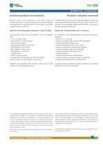
HC-D9 HCD9-04 INTRODUCTION Universal products and solutions - INTRODUZIONE Prodotti e soluzioni universali HC-D9 control valve belongs to the wide range of Hydrocontrol S.p.A. modular sectional valves and is capable of working with a maximum flow of 35 litres/min. at an operating pressure of 350 bar. Il distributore HC-D9 fa parte della vasta gamma della valvole componibili della Hydrocontrol S.p.A. ed è idoneo a funzionare con una portata massima di 35 litri/min. a una pressione di esercizio di 350 bar. Ideal for mini-excavators between 1 and 2.5 tons. Ideale per miniescavatori da 1 a 2,5...
Open the catalog to page 3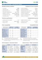
HC-D9 HCD9-04 GENERAL SPECIFICATIONS - CARATTERISTICHE GENERALI Standard working conditions Condizioni di lavoro standard • FLOW RATE . . . . . . . . . . . . . . . . . . . . . . . . . . . . 9 GPM • PORTATA NOMINALE . . . . . . . . . . . . . . . . . . .35 l/min • PRESSURE RATE . . . . . . . . . . . . . . . . . . . . . 5000 PSI • PRESSIONE NOMINALE . . . . . . . . . . . . . . . . .350 bar • MAX PRESSURE ON (T) . . . . . . . . . . . . . . . . . 290 PSI • PRESSIONE MAX SULLA LINEA (T) . . . . . . . . .20 bar • OPERATING TEMPERATURE . . . . . . . . . -25°C / +80°C • TEMPERATURA OPERATIVA . . . ....
Open the catalog to page 4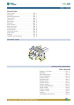
HC-D9 HCD9-04 INDICE - INDEX General index Order modality. . . . . . . . . . . . Dimensions . . . . . . . . . . . . . . Hydraulic specifications . . . . . Typical curves . . . . . . . . . . . . Inlet section . . . . . . . . . . . . . . Work section . . . . . . . . . . . . . Spool type . . . . . . . . . . . . . . . Spool actuation . . . . . . . . . . . Spool return action . . . . . . . . Work section type . . . . . . . . . Auxiliary valves . . . . . . . . . . . Intermediate sections . . . . . . Outlet section . . . . . . . . . . . . Features . . . . . . . . . . . . . . . . Installation and...
Open the catalog to page 5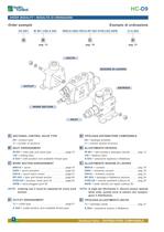
HC-D9 HCD9-04 ORDER MODALITY - MODALITÀ DI ORDINAZIONE Order example Esempio di ordinazione HC-D9/1 IR 001 (150) A G03 W001A H004 F001A RP G03 01PA(120) 05PB TJ A G04 B C D pag. 13 pag. 16 pag. 31 A USCITA SEZIONE DI LAVORO OUTLET ENTRATA WORK SECTION INLET A: SECTIONAL CONTROL VALVE TYPE A: TIPOLOGIA DISTRIBUTORE COMPONIBILE D9 = product type /1 = number of sections D9 = tipologia prodotto /1 = numero sezioni di lavoro B: INLET ARRANGEMENT B: ALLESTIMENTO ENTRATA IR 001 = inlet side and valve type . . . . . . . . .page 13 150 = setting (bar) A G03 = inlet position and available thread type...
Open the catalog to page 6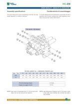
HC-D9 HCD9-04 ORDER MODALITY Assembly specifications - MODALITÀ DI ORDINAZIONE Caratteristiche di assemblaggio Tie rod kit allows the correct assembling of HC-D9. Tie rods lenght depends on number of sections. Il corretto allestimento del distributore componibile HC-D9 è garantito dal kit tirante caratterizzato dalla lunghezza variabile a seconda del numero delle sezioni. Tie rod kit - Kit tirante TIE ROD LENGHT (in) - LUNGHEZZA TIRANTE (mm) Type - Tipo /1 /2 /3 /4 /5 /6 /7 /8 /9 /10 /11 /12 mm 126 157 188 219 250 281 312 343 374 405 436 467 in 5 6,2 7,4 8,6 9,8 11 12,2 13,4 14,6 15,8 17...
Open the catalog to page 7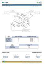
HC-D9 HCD9-04 DIMENSIONS - DIMENSIONI INSERIRE TITOLO ITALIANO - INSERIRE TITOLO INGLESE Standard thread Filettature standard PORT UTILIZZO (B) PORT UTILIZZO (B) OUTLET SCARICO (T) INLET INGRESSO (P) HYDRAULIC PILOT PILOTAGGIO IDRAULICO PORTS UTILIZZI thread - filettature (BSP) ISO-228 thread - filettature (SAE UN-UNF) ISO-725 Inlet - Ingresso P G 3/8 3/4”-16 UNF Ports - Utilizzi A - B G 3/8 3/4”-16 UNF Outlet - Scarico T G 1/2 7/8”-14 UNF Carry-over HPCO G 1/2 7/8”-14 UNF PORTS UTILIZZI thread - filettature (BSP) ISO-228 Hydraulic pilot Pilotaggio idraulico G 1/4 G 1/4 Ordering codes Sigle...
Open the catalog to page 8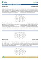
HC-D9 HCD9-04 HYDRAULIC SPECIFICATIONS - SPECIFICHE IDRAULICHE Parallel circuit Circuito Parallelo When the spool is operated it intercepts the switch gallery by diverting the flow of oil to service port A or B. If two or more spools are actuated at the same time, the oil will power the service port that has the lower load by selecting the path with the least resistance; by throtting the spools, the flow of oil can be divided between two or more service ports. HYDRAULIC SCHEMA A B Il cursore quando viene azionato, intercetta il canale di libera circolazione deviando il flusso d’olio agli...
Open the catalog to page 10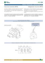
HC-D9 HCD9-04 HYDRAULIC SPECIFICATIONS Carry-over connection (HPCO) - SPECIFICHE IDRAULICHE Collegamento carry-over (HPCO) This option, available on all HC-D9, allows the monoblock to feed a second valve, by extending the free flow channel. In this configuration, the valve needs a separated port for the connection to tank. Questa opzione, di serie sul distributore HC-D9, permette il prolungamento del canale di libera circolazione all’esterno, alimentando così un secondo distributore. Il distributore così configurato necessita di uno scarico per le utenze. It is possible to transform...
Open the catalog to page 11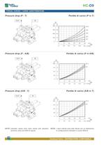
HC-D9 HCD9-04 TYPICAL CURVES - CURVE CARATTERISTICHE Pressure drop (P - T) Perdite di carico (P in T) OUT IN Δp psi bar 580 40 435 30 D9/9 290 20 D9/6 145 10 0 0 D9/12 D9/3 D9/1 0 10 20 30 40 0 2.6 5.3 7.9 10.6 Pressure drop (P - A/B) IN bar 232 16 174 12 116 8 58 4 0 0 D9/12 D9/1 0 10 20 30 40 0 2.6 5.3 7.9 10.6 Pressure drop (A/B - T) 50 l/min Qp 13.2 US-GPM Perdite di carico (A/B in T) IN Δp psi bar 232 8 174 6 116 4 58 2 0 0 D9/12 D9/1 0 NOTE: indicated values have been tested with standard sectional valve and W001A spools. 10 20 30 40 0 36 Qp 13.2 US-GPM Δp psi 10 l/min Perdite di...
Open the catalog to page 12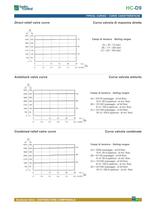
HC-D9 HCD9-04 TYPICAL CURVES Direct relief valve curve - CURVE CARATTERISTICHE Curva valvola di massima diretta Δp psi bar 5075 350 4350 300 3625 250 2900 200 2175 150 1450 100 725 50 Campi di taratura - Setting ranges (C) (A) = 30 / 110 (bar) (B) = 111 / 220 (bar) (C) = 221 / 350 (bar) (B) (A) 0 0 0 7 14 21 28 35 0 1.8 3.7 5.5 7.4 9.2 US-GPM l/min Qp Antishock valve curve Curva valvola antiurto Δp psi bar 5075 350 4350 300 3625 250 2900 200 2175 150 1450 100 725 50 Campi di taratura - Setting ranges (C) (A) = 20/100 (passaggio - at full flow) 10-A / 80-A (apertura - at min. flow) (B) =...
Open the catalog to page 13All WALVOIL catalogs and technical brochures
-
ELECTRONIC JOYSTICK
16 Pages
-
HC-SVM
24 Pages
-
Hydraulic remote control
96 Pages
-
HC-FL50
2 Pages
-
HC-M25
2 Pages
-
HC-SK6
2 Pages
-
HC-TR55
36 Pages
-
HC-M50 (Standard Version)
40 Pages
-
HC-D10
36 Pages
-
HC-M45
36 Pages
-
HC-NVD2
2 Pages
-
HC-MV99
36 Pages
-
HC-D4L
1 Pages
-
HC-D3L
1 Pages
-
HC-D6
52 Pages
-
HC-D4
56 Pages
-
HC-D3M
52 Pages
-
HC-D3
52 Pages
-
HC-D9
40 Pages
-
HC-SVM/SVE
24 Pages
-
HC - FL 50
2 Pages
-
HC - M 25
2 Pages
-
HC - SK 6
2 Pages
-
HC-BV50
36 Pages
-
product range
178 Pages
-
HC -TR55
36 Pages
-
HC -M50
40 Pages
-
HC -D10
36 Pages
-
catalog
96 Pages
-
Flow sharing
20 Pages
-
Proportional Valves
36 Pages
Archived catalogs
-
Fluid Power Solutions
68 Pages
-
HydroControl Brochure
8 Pages
-
Load Holding Valves
2 Pages
-
MiniMini-excavators
2 Pages


