
- Catalogs
- Walther Flender
- timing belts neoprenes

timing belts neoprenes

timing belts neoprenes
The document introduces the Walther Flender Group, a leader in timing belt drive systems, emphasizing their commitment to innovation and quality. They offer a comprehensive range of products, including custom solutions, backed by extensive engineering expertise and quality management certified to DIN EN ISO 9001:2000 standards.
The catalog details various PowerGrip® timing belts, including GT3, HTD®, and standard versions. These belts are designed for high power transmission and durability, suitable for a wide range of industrial applications. The PowerGrip® GT3 is highlighted for its advanced material composition, allowing it to transmit up to 30% more power than previous models.
Standard PowerGrip® timing belts meet most functional and environmental requirements. However, special versions are available for unique applications, such as cold-resistant, oil and heat-resistant, and electrically conductive belts. Custom dimensions and properties can be tailored to specific needs, though minimum purchase quantities may apply.
The document describes a case study where Walther Flender developed an electromechanical drive system for glass lifting in winter gardens. This system, using the PowerGrip® GT3 timing belt, offers efficient and safe handling of large glass panels, featuring overload protection and suitability for harsh construction site conditions.
The catalog provides detailed technical data for each belt type, including dimensions, power ratings, and suitable applications. It also includes information on timing belt pulleys and clamping sets, essential for optimal system performance.
Walther Flender's neoprene timing belts are versatile and reliable, suitable for various industries. Their commitment to quality and innovation ensures that they can meet the evolving demands of modern markets.
The PowerGrip® GT3 belt generation offers enhanced properties such as higher power density and improved tooth jumping behavior. It is designed for compact drive systems in various applications, including DIY machines, kitchen appliances, and precision servomotors. Larger pitches are suitable for high-performance systems in industries like tool, paper, and textile, meeting ISO 9563 standards for electrical conductivity and available in silicone-free versions for painting systems.
The GT3 timing belts are available in pitches of 2MGT3, 3MGT3, 5MGT3, 8MGT3, and 14MGT3, with special versions for specific requirements. They feature a fibreglass tensile member for high strength, a polychloroprene backing for durability, and nylon covering for wear resistance. The belts ensure positive power transmission, constant angular velocity, and high efficiency with low belt tension and bearing load.
The GT3 belts offer improved power transmission rates, reduced noise levels, and enhanced positioning accuracy. They are designed to minimize tooth jumping and maintain efficiency even at high starting torques. The belts are compatible with existing PowerGrip® GTMR/GT2 systems, requiring no technical modifications.
GT3 belts are manufactured in various lengths and widths, with options for special constructions. The pitch, pitch length, and width are critical dimensions, with specific teeth designs available for minimal backlash. Custom timing belt pulleys can be adapted to installation requirements, and further optimization can enhance drive unit functionality.
The document provides detailed tables for power output, permissible tangential loads, and belt dimensions. Calculations for belt drive units consider motor power output and load collectives, with safety factors and service life considerations. The power output data includes safety factors for achieving desired service life.
The PowerGrip® GT3 timing belts offer a versatile and efficient solution for various applications, with options for customization and optimization to meet specific requirements. The document emphasizes the importance of consulting application engineers for optimal system design.
This document provides detailed technical specifications and guidelines for the use of timing belts, specifically focusing on the PowerGrip® GT3 and HTD® timing belts by the Walther Flender Group. It includes information on belt dimensions, materials, and applications.
The document lists various timing belt specifications, including the number of teeth, pitch diameter, and outer diameter for different belt sizes. It also provides a table of belt designations with corresponding lengths and number of teeth.
The Twin Power GT2 timing belts are described, highlighting their construction, materials, and dimensions. These belts have symmetrical opposing teeth and are covered with a wear-resistant nylon fabric. They are suitable for transmitting rotary motions in both directions with high precision.
HTD® timing belts are advanced products used for over 30 years, known for their high torque transmission capabilities. They are available in various pitches from 3 mm to 20 mm, suitable for a wide range of applications. The document details the design and components of these belts, including the tensile member, neoprene backing, neoprene tooth, and nylon covering.
The HTD® timing belts offer positive power transmission, constant angular velocity, high efficiency, low belt tension, and maintenance-free operation. They are suitable for a large power and speed range, offering high performance and cost-effectiveness.
The document provides the main dimensions of the HTD® timing belts, including pitch, pitch length, and width. It also includes a table of standard widths and weights per metre for different pitches.
Technical data is provided for calculating permissible power output values based on belt width factors.
The document provides detailed specifications for timing belts, focusing on length correction factors, width factors, power output, and maximum permissible tangential loads. It includes data for timing belt pitches 3M and 5M, with standard widths and pitch diameters.
The document outlines the calculation of power output values by multiplying the values in the tables by the corresponding width factors. It also specifies that initial tensions for mounting the belts are included in the power output values.
The values listed apply to quasi-static loads, suitable for low-speed ranges (n ≤ 100 rpm) with timing belt pulleys having at least 24 teeth. The document emphasizes the importance of using the correct length and width factors for accurate power output calculations.
The tables provide operationally usable tangential loads for different belt widths and lengths. For example, for a timing belt pitch of 3M, the permissible tangential loads (Fzul) are 92 N for 6 mm, 152 N for 9 mm, and 272 N for 15 mm belt widths. Length factors range from 0.8 to 1.2 depending on the belt length, and width factors range from 0.09 to 1.0 depending on the belt width.
- Belt Widths: 6, 9, 15 mm for 3M pitch; 9, 15, 25 mm for 5M pitch.
- Length Factors: Vary based on belt length, affecting power output calculations.
- Width Factors: Influence the permissible power output values.
The document highlights the importance of selecting the correct number of teeth and pitch diameter for the small timing belt pulley to ensure optimal performance. It provides extensive tables for pitch diameters and outer diameters corresponding to the number of teeth.
This technical document serves as a comprehensive guide for selecting and calculating the specifications of timing belts, ensuring they meet operational requirements for specific applications.
The document provides detailed specifications for timing belts and pulleys, including belt widths, pitch diameters, and outer diameters. It includes tables with width factors for different belt sizes ranging from 3/8" to 3" and corresponding width factors from 0.28 to 3.36. The pitch diameter and outer diameter for various numbers of teeth are also listed.
Instructions are provided for calculating permissible power output values for different belt widths by multiplying the values in the tables by the corresponding width factors. The document emphasizes the importance of technical advice when dealing with high speeds and transmission ratios close to 1:1.
The document adheres to standard timing belt pitches, such as L (9.525 mm) and H (12.7 mm), and provides standard widths for timing belts, including 050 (1/2"), 075 (3/4"), and 100 (1").
It is recommended to avoid using cast iron pulleys for speeds greater than 30 m/s. The document suggests consulting technical advice for specific applications, especially when dealing with high-speed operations.
The tables provide power output values in kW for 1" belt width, starting with a number of meshing teeth ze=6. The permissible power output values for various belt widths can be obtained by multiplying the values in the tables by the corresponding width factors. The document includes detailed tables for different RPMs and numbers of teeth, providing a comprehensive guide for selecting the appropriate belt and pulley sizes.
Catalog excerpts

Neoprene timing belts Endless designs
Open the catalog to page 1
Walther Flender Group Neoprene timing belts – endless designs THE POWER OF [E]MOTION We set things in motion for you … … with innovative, new service concepts and individual system solutions which we develop with your cooperation. The Walther Flender Group stands for competence, experience and commitment. With leading edge technology and production expertise in drive and conveyor technology, clamping and bearing technology and the automotive sector. We would be glad to be able to do even more for you. For more than 70 years as a family business and market leader for timing belt drive systems,...
Open the catalog to page 2
WALTHER FLENDER GRDUP NEDPRENE TIMING BELTS — ENDLESS DESIGNS PAG TABLE OF CONTENTS page Twin Power, version GT2 22 Twin Power, version HTD® 38 General information on PowerGrip® timing belts_ _^ Timing belt pulleys_ 67 Standard line of timing belt pulleys_ 73 TL bushes for PowerGrip® HTD® timing belt pulleys_ _ PowerGrip® standard _ Project data sheet_ 103 Please note that not every timing belt listed in the catalog is in stock and that you may have to expect longer delivery times or minimum purchase quantities in some cases. For further information on delivery conditions for the desired timing...
Open the catalog to page 3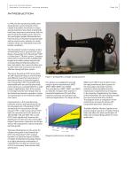
Walther Flender Group Neoprene timing belts – endless designs Introduction In 1946, the first synchronous belts were developed for synchronization of the needle and bobbin movement in Singer sewing machines. Since then, timing belts have been improved continuously with the goal of achieving higher power transmission and higher speeds. Meanwhile they have become an essential component part and are used in every industry as a drive medium which can withstand even problematic conditions. This PowerGrip® product catalog contains all information that is necessary for calculating a PowerGrip® GT3,...
Open the catalog to page 4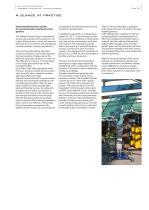
Walther Flender Group Neoprene timing belts – endless designs A glance at practice Electromechanical drive system for convenient glass roofing of winter gardens The Walther Flender Group is developing an electromechanical drive system for use in glass lifting systems, which will meet the demands for a convenient and safe glazing of winter gardens, canopies and atriums. The trend toward building with glass continues unbroken. Due to the improved thermal insulation of glass panels, the desire for large glass surfaces is on the rise. The difficulty, is of course, in the handling of such large glass...
Open the catalog to page 5
Walther Flender Group Neoprene timing belts – endless designs Special versions Standard PowerGrip® timing belts (with respect to dimensions, design and materials) are sufficient in most cases to fulfil the requirements for functionality and environmental conditions, as well as spatial considerations. Throughout many years of experience in the segment of mechanical drive technology, it has often been confirmed that standard belts, properly dimensioned, can also be used in applications where it at first would seem questionable to use them. Therefore, you should take advantage of our knowledge,...
Open the catalog to page 6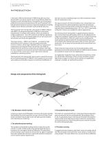
Walther Flender Group PowerGrip® GT3 Introduction In the early 1990s the PowerGrip® GTMR timing belt was introduced, which was clearly superior to all conventional rubber timing belts in terms of performance. Through the use of innovative production processes and parameters, the new PowerGrip® GT3 belt generation features numerous improved properties, including a higher power density and better tooth jumping behaviour. The PowerGrip® GT3 timing belts with pitches of 2MGT3, 3MGT3 and 5MGT3 are designed especially to fulfil the construction requirements of compact drive systems, which are needed...
Open the catalog to page 9
Walther Flender Group PowerGrip® GT3 General features Positive power transmission Tooth jumping behaviour The positive meshing of the GT3 belt teeth in the teeth of the drive pulleys ensures the positive synchronous transmission of power. Slippage and related deviations in speed are eliminated. The considerable improvement in the tooth jumping behaviour of the GT3 timing belt as compared to belts with similar dimensions has several advantages: a. Safety at high starting torques. Constant angular velocity The GT3 timing belt wraps around the timing belt pulley in a circular pattern and not in...
Open the catalog to page 10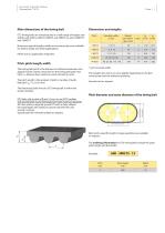
Walther Flender Group PowerGrip® GT3 Main dimensions of the timing belt GT3 timing belts are manufactured in a wide range of lengths and widths with pitches 2MGT3, 3MGT3 and 5MGT3, as well as 8MGT3 and 14MGT3. Dimensions and weights Pitch Weight per metre* glass cord Numerous special lengths, widths and constructions are available for diverse single and serial applications. Please ask our application engineers. Pitch, pitch length, width The timing belt pitch is the distance in millimetres between two adjacent tooth centres, measured on the timing belt pitch line: Pitch t = distance from centre...
Open the catalog to page 11
Walther Flender Group PowerGrip® GT3 Technical data Timing belt pitch 2MGT3 Calculation of the dimensions and design of belt drive units can be based on the motor side (motor power output) and on the load side (load collectives). Both calculations – depending on the existing safety factors, desired service life or any load-side efficiency losses – can result in designs for drive systems with different over- all widths. In addition to the load value calculation, therefore, we also recommend that you use the following power output table to compare the actual tangential loads with the maximum permissible...
Open the catalog to page 12
Walther Flender Group PowerGrip® GT3 For ordering information see page 11.
Open the catalog to page 13
Walther Flender Group PowerGrip® GT3 Timing belt pitch 3MGT3 Calculation of the dimensions and design of belt drive units can be based on the motor side (motor power output) and on the load side (load collectives). Both calculations – depending on the existing safety factors, desired service life or any load-side efficiency losses – can result in designs for drive systems with different over- all widths. In addition to the load value calculation, therefore, we also recommend that you use the following power output table to compare the actual tangential loads with the m aximum permissible loads....
Open the catalog to page 14All Walther Flender catalogs and technical brochures
 WF_TM_Nano
1 Page
 ML Clamping Sets
30 Pages
 PolyChain_timingbelts
48 Pages
 frequency inverter Serie M/N
24 Pages
 Flatbelts WF Lift Power
12 Pages
Archived catalogs

- Electromotor
- Synchronous motor
- Alternating current motor
- Multipole motor
- Asynchronous motor
- Planetary gearbox
- Coaxial gearhead
- EC motor
- Electromotor for industrial applications
- Power transmission belt
- Three-phase motor
- 24 V motor
- Compact gearhead
- 4-pole motor
- 2-pole motor
- Flexible coupling
- Gear train gear reducer
- 12 V motor
- Gearbox for industrial applications