
- Catalogs
- Walther Flender
- Timin belt P o w e r G r i p ® HTD®

Timin belt P o w e r G r i p ® HTD®

Timin belt P o w e r G r i p ® HTD®
HTD synchronous belt drives are globally recognized for their ability to handle high torque loads. They feature a semicircular tooth shape, glass-fiber tensile elements, and a nylon finish, enhancing power transmission. Available in five tooth pitch dimensions (3 mm to 20 mm), they are suitable for various applications, including heat and cold-resistant versions and special designs for conveyor systems.
HTD belts ensure positive power transmission with no slippage, maintaining constant angular velocity and high efficiency (approximately 98% in two-sprocket configurations). They require low belt tension, reducing bearing load and allowing for lighter machine components. The belts are maintenance-free, with a long lifespan, and offer a wide range of power and speed capabilities.
Synchronous Belts: HTD belts have a newly developed tooth profile for higher loading capacity, consisting of wear-resistant teeth, fiberglass tensile members, neoprene backing, and a nylon facing for low friction and wear protection.
Belt Dimensions and Weights: Belt lengths range from 127 mm to over 1779 mm, with specific tolerances. Standard widths and weights per meter are provided for different pitch values.
Special Designs: Custom designs are available for specific applications, including cold-resistant, heat-resistant, oil-resistant, and static conductive versions. Special widths and lengths can be manufactured upon request.
Standard and special-design sprockets are available, with manufacturing guidelines covering materials, recommended widths, and tolerances.
Guidelines include adjustable and fixed center distances, idlers, shaft alignment, mounting elements, and maintenance tips. Belt tensions and troubleshooting advice are also provided.
Includes general calculation formulae, factors, methods, and examples for determining power values and belt lengths. Standard sprocket lines and TaperLock bushings are detailed.
A project data sheet is included for developing ideal solutions with the application engineering department.
The document outlines formulas for calculating circumferential force, revolution speed, circumferential speed, and various forces such as acceleration, braking, lifting, and frictional forces. It also provides equations for mass calculations, including reduced sprocket mass and sprocket mass.
An overall service factor (SG) is required for drive system calculations, determined by several factors including loading factor (S1), teeth-in-mesh factor (S2), transmission ratio supplement (S3), flexure factor (S4), special service factor (S5), belt length factor (S6), and width factor (S7).
Guidelines for selecting loading factors based on the type of driven equipment and duty cycle are provided, emphasizing the importance of consulting with application engineers in critical situations.
A step-by-step method is provided for calculating the design power and selecting the appropriate belt and sprocket sizes, including determining the number of teeth in mesh and calculating the overall service factor.
An example illustrates the calculation process for a specific drive system, including the selection of belt pitch, sprocket size, and belt length.
Tables for determining permissible power values based on belt width and length, as well as a table for synchronous belts in special lengths, are included.
The document highlights the importance of selecting the correct service factors and consulting with engineers for applications involving extreme conditions or specific requirements. Detailed tables for selecting the appropriate belt and sprocket sizes based on power and speed requirements are provided.
Detailed specifications for PowerGrip® HTD® Synchronous Belt Drives focus on various sprocket ranges and their respective dimensions, materials, and weights. Information on different pitch sizes and gear ring widths, as well as the materials used for construction, is included.
Steel is used up to certain sizes, with aluminum and GG 15 gray casting used for larger sizes.
The document covers 5 mm, 8 mm, and 14 mm pitch sizes, each with specific gear ring widths and overall widths.
Varying widths are specified for different pitch sizes, ranging from 14.5 mm to 187 mm.
Each sprocket is identified by a designation code, number of teeth, outside diameter, preliminary bore, and maximum finished bore. Weights are provided for each sprocket, indicating the material and construction type.
Sprockets are available for TaperLock mounting bushings, with specific styles and bushing sizes detailed. Different flange versions are noted, such as 6F, 6W, and 10A, indicating variations in design and application.
Tables provide comprehensive data on sprocket dimensions, including outside diameter, bore sizes, and weights. Each table is organized by pitch size and gear ring width, allowing for easy comparison and selection based on application needs.
Material selection is crucial for performance, with steel and aluminum used for different applications based on size and load requirements. Understanding the gear ring width and overall width is essential for ensuring compatibility with specific belt drive systems.
Catalog excerpts
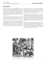
HTD synchronous belt drives are technically refined products usedaround the world. They have demonstrated their utility in more than 20 years of service. The H igh T orque D rive belt exhibits alltransmit of the conventional synchronous belt drive and is further distinguished by its capability to greater torque loads. The semicircular tooth shape, the glass-fiber tensile element and the nylon finish on the teeth have brought a considerable increase in power transmission capabilities compared with drives using conventionally belts.Building on the standard program, a broad line of types hasbeen...
Open the catalog to page 3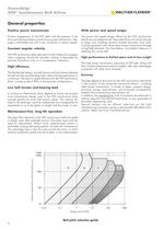
The high power transmission capacities of HTD belt, along withtheir compact dimensions and low weights, offer clear advantages compared with other drive concepts. The high degree of economy for the HTD synchronous belt drivesis the product of the properties mentioned above including ideal power transmission, a variety of types, compact design, minimum energy requirements, environmental acceptability, freedom from maintenance requirements, etc. In addition, the High performance in limited space and at low weight Economy > Positive engagement of the HTD teeth with the grooves of thedrive sprocket...
Open the catalog to page 4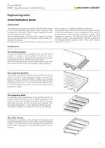
The greater power transmission capacity of the HTD belts is basedon the newly developed tooth profile which, thanks to more favorable force distribution, allows a higher loading on the teeth as they engage with the sprocket. The wear-resistant teeth are finished with a rugged nylon fabric and are unitized with the proven fiberglass tensile members in a vulcanization process. The high performance of the HTD belt now permits use in widertorque ranges, in a multitude of different applications.The patented tooth profile for the HTD belt, the product of years of trials and development, ensures engagement...
Open the catalog to page 5
Standard-design PowerGrip HTD synchronous belts (standardizeddimensions, structure and materials) will in most cases satisfy the requirements dictated by functional needs and environmental influences and by the space available in the application. Years of experience in the field of mechanical drive technology have shown again and again that standard belts of appropriate dimensions can often also be employed even where the operating parameters at first made their use seem questionable. That is why you should draw upon our vast knowledge, since standard designs, available from stock at short notice,...
Open the catalog to page 7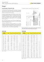
D: Minimum material overhang for proper flange fitting The PowerGrip HTD synchronous belt drive systems incorporatea sprocket which is fitted with flanges on both sides to guide the belt. In many cases the smaller sprocket will be selected for this purpose, in the interest of cost savings.It should be noted, however, that the driven sprocket should infact always be fitted with flanges on both faces, since it is easier to guide the slack section where it runs onto the sprocket. Both sprockets, or the larger of the two, should be fitted with flanges on both sides where the distance between centers...
Open the catalog to page 12
In the interest of securely attaching the sprocket to the shaft thereare aside from the conventional groove and key connectors ֖ various frictional, detachable tightening elements available to fit all the standard bore diameters.In addition to the TL (TaperLock Simple installation and removal The unit is assembled or disassembled by tightening or loosening the screws with conventional tools. Using a torque wrench makes it possible to achieve exact tightening torque.Oil the screws sparingly before installing them. Do not use oilcontaining molybdenum sulfide; never use grease. > ֮ ) bushings which...
Open the catalog to page 16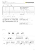
M > S NmTightening torque for the set screws M > t NmMaximum transmittable torque P > ax kNAxial force which can be transmitted P > 2 W N/mm Permissible surface pressure on the shaft P > 2 N N/mm Permissible surface pressure on the hub P > O kNAxial force required to achieve the frictional connectionP > tot kNTotal axial force > The minimum outside diameter for the hub is obtained by multiplying the outside diameter of the bushings by the factors shown in the table. These factors are dependent upon the elongation (permanent deformation) limit of the hub material and upon the surface pressure...
Open the catalog to page 17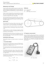
PowerGrip HTD synchronous belts incorporate a tensile memberwhich is stable in the longitudinal dimension and will permit no permanent elongation during operation. It is for this reason that there is no need to correct belt tensioning; no special maintenance is required.There is, however, a danger if the synchronous belts, which shouldbe laid very loose during storage, could be crimped or folded. This can cause damage to the cords and a loss of power transmission capacity. Do never crimp sharply.We recommend leaving the synchronous belts in the factorypackaging until they are installed and, during...
Open the catalog to page 23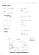
Torque Frictional force > 3 d M =P 9.55 10 =F > U w 3 [Nm]n2 10 F > R = m g [N] Mass Power շ v[kW]9.55 10 m = m > L + m > R + m > Zred [kg]mit m P =M n=F > U 3 = I m 10 > 3 R W G Reduced sprocket mass Circumferential force > Z B2 3 3 m > Zred =m ( 1 + d )[kg]2d F > U =P 10 =M 2 10 [N]vd > a2 w Sprocket mass Revolution > a2 ז d > B2 ) 7 B > 3 m > Z =(d > 6 [kg]4 · 10 n =19.1 10 v[min > -1 ]d > w ς = Density Circumferential speed nm19.1 10 Elongation v =d > w 3 sec ∆ I 100[%]I = > t Acceleration force Specific spring constant F > a = m a [N] 100[N] C > admissible spec =F Braking...
Open the catalog to page 26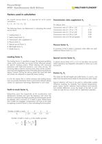
An overall service factor S > G is required for drive systemcalculations:S > 3 G = S > 2 (S > 1 + S > 3 + S > 4 - S > 5 )The following factors are determinant in calculating the overallservice factor:1. Loading factor S For step-up ratiosS > 3 Transmission ratio of 1.00 to 1.24זTransmission ratio of 1.25 to 1.740.10Transmission ratio of 1.75 to 2.490.20Transmission ratio of 2.50 to 3.490.30Transmission ratio of 3.50 and greater0.40 > 1 2. Teeth-in-mesh factor S > 2 3. Transmission ratio supplement S > 3 4. Flexure factor S > 4 5. Special service factor S > 5 4 6. Belt length factor S > 6 7. Width...
Open the catalog to page 27All Walther Flender catalogs and technical brochures
 timing belts neoprenes
108 Pages
 WF_TM_Nano
1 Page
 ML Clamping Sets
30 Pages
 PolyChain_timingbelts
48 Pages
 frequency inverter Serie M/N
24 Pages
 Flatbelts WF Lift Power
12 Pages
- Electromotor
- Synchronous motor
- Alternating current motor
- Multipole motor
- Asynchronous motor
- Planetary gearbox
- Coaxial gearhead
- EC motor
- Electromotor for industrial applications
- Power transmission belt
- Three-phase motor
- 24 V motor
- Compact gearhead
- 4-pole motor
- 2-pole motor
- Flexible coupling
- Shaft shaft coupling
- Gear train gear reducer
- 12 V motor
- Gearbox for industrial applications