Overview Relays and Optocouplers
1 /36Pages

Overview Relays and Optocouplers
1 /36Pages
Catalog excerpts

RELAYS AND OPTOCOUPLERS Application Overview
Open the catalog to page 1
CONNECTION TECHNOLOGY This connection technology is included in the following: CAGE CLAMP? This connection technology is included in the following:
Open the catalog to page 2
Relays / Optocouplers SELECTION CRITERIA FOR RELAYS It’s in the details LONG CABLES AND 2-WIRE SENSORS Reliably switch despite coupling MODERN LIGHTING WITH ELECTRONIC CONTROL GEAR Brief current peaks – fatal consequences FUNCTIONAL SAFETY Detect errors in safety-related circuits THE CONTACT MATERIAL IS CRUCIAL Small circuit loads / harsh environment RELAYS WITH MANUAL OPERATION Switch manually and electrically RELAYS WITH A WIDE INPUT VOLTAGE RANGE Versatile RAIL-SPECIFIC REQUIREMENTS Master voltage fluctuations Ambient operating temperature and mechanical influences SWITCHING DC LOADS Improvement...
Open the catalog to page 3
FEATURES AND ADVANTAGES Relays / Optocouplers Relay or Optocoupler? Relay Optocoupler/Solid-State Relay • Electrically isolate input and output circuits • Adjust different signal levels • Amplify and/or multiply signals Immunity to electromagnetic interference and transient voltages Long service life — no mechanical wear on contacts High, short-term overload on both input and output sides without losing functionality High switching frequency due to short switch-on and switch-off times Minimal switching loss/high switching power Unfazed by shock and vibration A single module switches both direct...
Open the catalog to page 4
Distinguishing between Optocoupler and Solid-State Relay Solid-State Relay - Can be replaced in case of repair A large number of variants enhances application flexibility Seamless change from electronic to electromechanic and range switching element
Open the catalog to page 5
SELECTION CRITERIA FOR RELAYS It’s in the details In industrial applications, relays are proven interface modules that can handle a variety of tasks. However, some points must be considered when selecting the right relay module. These points include the nominal voltage of the coil, as well as the number of relay break contacts, make contacts and changeover contacts. The contacts are important for the service life. The contact material has to be selected depending on whether inductive, capacitive or resistive loads will be connected. This application overview provides important information for...
Open the catalog to page 6
3) Switching time Response time; drop-out time; switching frequency; bounce time 4) Mechanical properties Vibration resistance; shock resistance; size and space 5) Other criteria Ambient temperature; dielectric strength; mounting conditions, IP degree of protection; approvals
Open the catalog to page 7
LONG CABLES AND 2-WIRE SENSORS Reliably switch despite coupling Reliability 24/7: WAGO’s sockets that have a miniature switching relay and base load module ensure safety and dependability at voltage levels below an application’s release voltage. To switch on, relay modules require the nominal voltage U . For operation, however, the holding voltage at only 15 % of the nominal voltage is sufficient. In standard circuits, all relay modules operate reliably. In circuits with long, parallel lines, in circuits with active 2-wire sensors or with digital AC control outputs, however, a low holding voltage...
Open the catalog to page 8
Application example, line capacity (level measurement) Application example, 2-line sensors (parcel load detection) I Nominal Input Voltage V Limiting Continuous Current Relay module with 1 changeover contact, with integrated base load module Relay module with 1 changeover contact, with integrated base load module and gold contacts *To prevent the gold layer from being damaged, 30 VDC switching voltages and 50 mA currents shall not be exceeded. Higher switching power eventually evaporates the gold layer. The resulting deposits in the housing may reduce the service life.
Open the catalog to page 9
MODERN LIGHTING WITH ELECTRONIC Brief current peaks – fatal consequences When switching on lamps, substantial current peaks briefly occur. The unwanted effect of wear and contact erosion can be prevented by lamp load relays. Equipped with electronic control gear (ECG), modern lights offer numerous advantages. They generate flicker-free light with high levels of efficiency. Both in planning new and replacing old lighting systems, the inrush current of the ECG must be a central focus. A capacitor in the input circuit of many ECGs causes a substantial current peak when switched on that can exceed...
Open the catalog to page 10
CONTROL GEAR Relay selection for lamp loads Nominal Input Voltage V Limiting Continuous Current Relay module with 1 changeover contact and status indication, max. inrush current 120 A / 50 ms Relay module with 1 make contact and status indication, max. inrush current 165 A / 20 ms Solid-state relay module, zero voltage switch Solid-state relay module, zero voltage switch Relay with 1 make contact, Manual/OFF/Auto switch with feedback contact A = Automatik (AUTO) 0 = AUS 1 = Manuell EIN (MAN) 14
Open the catalog to page 11
FUNCTIONAL SAFETY Detect errors in safety-related circuits Signal monitoring: Relays with force-guided contacts make it possible to quickly detect errors such as opening failures. To comply with relevant policies and regulations for functional safety, the use of special components is compulsory. These components must meet strict requirements. For relay modules, force-guided contacts with at least one break contact and make contact are required. They must be connected mechanically so that break contacts and make contacts cannot be closed or opened at the same time. This allows errors due to opening...
Open the catalog to page 12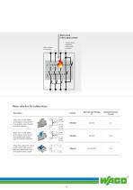
Short circuit Auxiliary break safety circi Relay selection for safety relays
Open the catalog to page 13
THE CONTACT MATERIAL IS CRUCIAL Small circuit loads / harsh environment Prevent malfunctions: Relays with hard, gold-plated contacts are particularly well suited for switching small loads. Standard relay contacts are normally made of silver alloys such as silver nickel, silver tin oxide or silver cadmium. They are well suited for use in a variety of applications. However, they are limited to small loads, currents and voltages. The surfaces of the sliver alloys are prone to oxidation, which leads to an increase in contact resistance. It is not a problem when switching larger loads because ever...
Open the catalog to page 14All WAGO catalogs and technical brochures
 789-665
5 Pages
 752-8400
3 Pages
 Assembled jumper bar; 2-way
2 Pages
 Assembled jumper bar; 3-way
2 Pages
 Empty housing; M8; gray
5 Pages
 WAGO Power Supplies
236 Pages
 WAGO Marking
92 Pages
 Setup unit
1 Page
 THR Technology
8 Pages
 KNX IP 1.1 US
6 Pages
 Electrical Interconnection
56 Pages
 Safety Flyer
8 Pages
 Speedway Brochure 4.2 US
28 Pages
 Telecontrol Technology 2.0 US
36 Pages
 WAGO Controllers US
12 Pages
 Building Automation
40 Pages
 PCB/MCS 12/13 GB
636 Pages
 Supplement Interconnection 01/14 US
116 Pages
 Supplement AUTOMATION 01/14 US
242 Pages
 Lighting and Equipment 2.0 US
524 Pages
 AUTOMATION12/13 GB
674 Pages
 Interface Electronic12/13 GB
460 Pages
 PSF 4.1 E Product Shortform (S 773)
219 Pages
 Supplement AUTOMATION 01/13 US
131 Pages
 WINSTA® 12/13 GB
268 Pages
 Supplement Interconnection
88 Pages


Archived catalogs
 References-Railway Engineering
152 Pages
 References-Power Engineering
92 Pages
 References-Marine Engineering
120 Pages
 References-Water and Sewage
23 Pages


- Connector
- Power supply unit
- DC power supply
- AC/DC power supply
- Data connector
- Transformer
- Ethernet switch
- LCD screen
- Monitor with touchscreen
- Electrical power supply connector
- Industrial monitor
- Intel® Core™ PC
- Dry transformer
- Industrial network switch
- HDMI PC
- Digital I/O
- Panel-mount screen
- Process software
- Windows software
- Computer-aided design software