


Zip 52

Zip 52
This manual provides operating instructions for the ZIP 52 Finishing diaphragm pump, covering models such as ALU SP, INOX SP, ACETAL SP, and PERFECT FLOW SP. It includes safety instructions, product descriptions, and warranty information.
Operators must ensure electrical safety, qualified personnel, and a secure work environment. Key safety measures include using anti-static equipment, proper handling of spray units, and grounding to prevent electrostatic discharge. Hazardous materials require careful handling, and hot surfaces should be avoided.
The warranty covers defects in materials and workmanship for 36 months, extendable by 24 months with registration. Exclusions include wear and tear, improper use, and unauthorized modifications. Claims require prompt action and proof of purchase.
The pump is designed for process liquid materials and is compatible with various construction materials. It includes components like a material pump, air motor, and suction hose. Technical data specifies materials used, operating pressures, and temperature ranges.
Proper pump setup and grounding are required for installation. Safety regulations must be followed during startup, operation, and shutdown. Regular maintenance and cleaning are essential for functionality.
Troubleshooting guides address common issues. Regular maintenance includes filter cleaning and machine upkeep to prevent operational failures.
A range of accessories is available for different pump configurations. Spare parts can be ordered as needed, with detailed diagrams for assembly and repair.
Contact information for service centers is included for warranty claims and repairs.
Detailed dimensions and connections for various models of the ZIP52 Finishing equipment are provided, with key dimensions in millimeters and inches, and specific connection types noted.
The diaphragm pump operates using compressed air, with two diaphragms connected by a shaft, creating driving and pumping chambers. Compressed air alternates between chambers to facilitate the pumping action. The air motor must not exceed specified pressure levels.
The pressure regulator section includes components like air pressure reducers, manometers, and connections for both air and fluid. Technical details for the Fine Flow Controller are specified, including material specifications and performance parameters.
Installation procedures differ slightly between models. Specific connections for air and paint delivery are required for each model.
Proper earthing procedures are outlined, including cable specifications and connection points to ensure safety and prevent static discharge.
Safety checks before starting include ensuring all connections are secure and pressures are within permissible limits. Emergency stopping procedures involve closing air valves and releasing pressure.
Initial washing with solvent is recommended to remove testing fluid residues. Regular maintenance includes cleaning filters and ensuring no blockages in the system.
Instructions for operating the pump during painting include setting pressures and handling breaks in work. Special attention is given to handling two-component materials and ensuring the system is free of blockages.
Proper shutdown involves cleaning the system to prevent material from drying and sticking. A step-by-step cleaning process is outlined to maintain the equipment.
For long-term storage, thorough cleaning and corrosion protection are necessary. The system should be filled with preserving oil to maintain its condition.
- The pump does not start: Check the line, air cutoff valve, air treatment group, and valve openings. Increase pressure and reopen the air on-off valve rapidly.
- The unit is working but no liquid is coming out: Clean the filter, check liquid level and suction pipe.
- Poor spray pattern: Refer to gun instructions.
- Discontinuous product flow: Check for clogs in the suction pipe and cavitation in the pump.
- Decreased pump delivery: Check for obstructions, product characteristic variations, and ice formation in air outlet pipes.
- Frequent unit stops: Increase air pressure, adjust lubricator output, and use antifreeze if necessary.
- Equipment remains operational with closed delivery valve: Check product cutoff valve and outlet valve seals for impurities.
1. Follow shutdown procedures as per paragraph 5.3.3.
2. Daily check and replace hoses, tubes, and couplings if necessary.
3. Clean filters daily and when changing paint colors. Specific cleaning steps include using solvents and compressed air.
Ensure compressed air input valve is closed and pressure is released before cleaning. Clean both suction and delivery circuit filters using solvents and compressed air.
- Diaphragm Replacement (Preventive): Follow a detailed sequence for disassembly and reassembly, ensuring proper lubrication and tightening.
- Diaphragm Replacement (Due to Breakage): Clean internal parts and check seals and reversing valve condition.
- Cleaning/Replacement of Valves: Remove manifolds, extract components, and check for wear.
Details on accessories for specific models and spare parts lists are provided, including wall support, stand kits, and trolley kits with corresponding part numbers and quantities.
Catalog excerpts
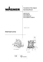
Translation of the original Operating Manual ZIP52 ALU SP ZIP 52 INOX SP ZIP 52 ACETAL SP ZIP 52 PERFECT FLOW SP Diaphragms pump
Open the catalog to page 1
OPERATING MANUAL ABOUT THESE INSTRUCTIONS Languages Warnings, notes and symbols in these instructions GENERAL SAFETY INSTRUCTIONS Safety instructions for the operator Electrical equipment Personnel qualifications A safe work environment Safety instructions for staff Safe handling of WAGNER spray units Earth the unit Material hoses Cleaning Handling hazardous liquids, varnishes and paints Touching hot surfaces Correct use Use in an explosion hazard area Correct use Explosion protection identification Max. surface temperature Safety regulations PRODUCT LIABILITY AND WARRANTY Scope of guarantee Guarantee...
Open the catalog to page 3
OPERATING MANUAL Safety regulations Emergency stopping Washing Unit pressure tightness test Work Spraying Painting hints Working breaks Shutting down and cleaning Storing for longer periods of time FAULT LOCATION, MAINTENANCE AND REPAIR Trouble shooting and solution Maintenance Filter cleaning operations Machine maintenance ACCESSORIES Accessories only for 2301832, 2301836, 2301837 Pump zip 52 finishing with wall supporting kit cod. T760.00M Overall dimensions cod. T760.00M Pump zip 52 finishing with stand kit cod. T760.00S Overall dimensions cod. T760.00S Pump zip 52 finishing with handle+wheels...
Open the catalog to page 4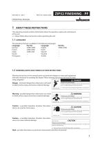
OPERATING MANUAL ABOUT THESE INSTRUCTIONS WARNINGS, NOTES AND SYMBOLS IN THESE INSTRUCTIONS
Open the catalog to page 5
OPERATING MANUAL GENERAL SAFETY INSTRUCTIONS SAFETY INSTRUCTIONS FOR THE OPERATOR ELECTRICAL EQUIPMENT PERSONNEL QUALIFICATIONS A SAFE WORK ENVIRONMENT Ensure that the floor of the working area is anti-static in accordance with EN 50053 Part 1 §7-2. Ensure that all persons within the working area wear anti-static shoes, e.g. shoes with leather soles. Ensure that during spraying, persons wear anti-static gloves so that they are earthed via the handle of the spray gun. Customer to provide paint mist extraction systems conforming to local regulations. Ensure that the following components of a safe...
Open the catalog to page 6
OPERATING MANUAL SAFE HANDLING OF WAGNER SPRAY UNITS The spray jet is under pressure and can cause dangerous injuries. Avoid injection of paint or cleaning agents: Never point the spray gun at people. Never reach into the spray jet. Before all work on the unit, in the event of work interruptions and functional faults: – Switch off the energy/compressed air supply – Secure the spray gun against actuation. – Relieve the pressure from the spray gun and unit. – By functional faults: If possible, remove the defect as described in chap. „Trouble shooting“, otherwise apply to an authorised after-sale...
Open the catalog to page 7
OPERATING MANUAL HANDLING HAZARDOUS LIQUIDS, VARNISHES AND PAINTS
Open the catalog to page 8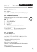
OPERATING MANUAL USE IN AN EXPLOSION HAZARD AREA EXPLOSION PROTECTION IDENTIFICATION As defined in the Directive 94/9/CE (ATEX 95), the unit is suitable for use in areas where there is an explosion hazard. II 2G IIB T4 Communautés Européennes Symbol for explosion protection Unit class II Category 2 (Zone 1) Ex-atmosphere gas Explosion class Temperature class: maximum surface temperature < 135°C; 275°F. Max. surface temperature: Permissible ambient temperature: same as the permissible material temperature see under Technical data, Section 4.3.2 SAFETY REGULATIONS
Open the catalog to page 9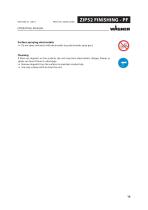
OPERATING MANUAL
Open the catalog to page 10
OPERATING MANUAL PRODUCT LIABILITY AND WARRANTY (STATUS 01.02.2009) All Wagner professional colour application devices (hereafter referred to as products) are carefully inspected, tested and are subject to strict checks under Wagner quality assurance. Wagner exclusively issues extended guarantees to commercial or professional users (hereafter referred to as “customer”) who have purchased the product in an authorised specialist shop, and which relate to the products listed for that customer on the Internet under www.wagner-group.com/profi-guarantee. The buyer’s claim for liability for defects from...
Open the catalog to page 11
OPERATING MANUAL 3.4 EXCLUSION OF GUARANTEE Guarantee claims cannot be considered - for parts that are subject to wear and tear due to use or other natural wear and tear, as well as defects in the product that are a result of natural wear and tear, or wear and tear due to use. This includes in particular cables, valves, packaging, jets, cylinders, pistons, meanscarrying housing components, filters, pipes, seals, rotors, stators, etc. Damage due to wear and tear that is caused in particular by sanded coating materials, such as dispersions, plaster, putty, adhesives, glazes, quartz foundation. -...
Open the catalog to page 12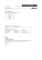
OPERATING MANUAL Herewith we declare that the supplied version of: Pneumatic pumps with article no. 2301832 2301836 2301837 2301838 Complies with the following provisons applying to it: 2006/42/EC Applied standards, in particular: UNI EN 12100-1
Open the catalog to page 13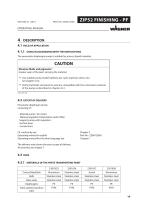
OPERATING MANUAL USING IN ACCORDANCE WITH THE INSTRUCTIONS The pneumatic diaphragm pump is suitable for process liquid materials. CAUTION Abrasive fluids and pigments ! Greater wear of the parts carrying the material. Use suitable pump model (delivery per cycle, material, valves, etc.) see chapter 4.3.2. Verify that fluids and solvents used are compatible with the constrution material of the pump as described in chapter 4.3.1. SIHC_0067_GB Pneumatic diaphragm pump consisting of: - Material pump / Air motor Material regulator/Antipulsator and/or filter Support pump with regulators Suction hose...
Open the catalog to page 14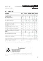
OPERATING MANUAL TECHNICAL DATA Transmission ratio Ø air inlet connection (female) Sound power at max. flow rate feeding 8 bar; 116 psi *. Sound pressure equivalent to max.flow rate feeding 8 bar; 116 psi *. Sound pressure equivalent to 50 cycles/min feeding 5 bar; 72,5 psi*. Material outlet connection (female) (M16x1,5) Weight Max. material pressure at pump inlet Range of material temperature Range of the ambient temperature Allowable sloping position at work * A rated sound pressure level measured at 1m distan
Open the catalog to page 15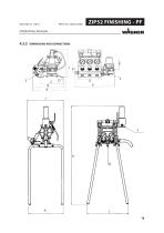
OPERATING MANUAL
Open the catalog to page 16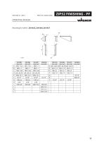
OPERATING MANUAL
Open the catalog to page 17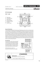
OPERATING MANUAL Diaphragms Connecting shaft Check valves Driving chambers Pumping chambers Air motor Inversion valve General information The principle lying behind the functioning of diaphragm pumps driven by compressed air is just as simple as it is effective. Two diaphragms (A), which are connected to one another by means of a connecting shaft (B) so as to be integral, divide two adjacent capacities into four chambers. The inner ones function as driving chambers (M) while the outer ones function as pumping, chambers (P). A pneumatic distributor alternately conveys compressed air into one of...
Open the catalog to page 18All WAGNER catalogs and technical brochures
 Brochure PEM-X1 CG
4 Pages
 Brochure Manual application
3 Pages
 Corona and Tribo Guns
10 Pages
 Brochure Cobra
4 Pages
 Press release IceBreaker
3 Pages
 STATIONARY Wood- & Metalworking
11 Pages
 Manual powder coating
3 Pages
 PXS Powder Centers
2 Pages
 TOPFINISH DD10
2 Pages
 FENCE & DECKING SPRAYER
36 Pages
 C-Line
6 Pages
 WOOD- & METALWORKING
12 Pages
 Unica AME
4 Pages
 Flyer EvoMotion-Revers AME
2 Pages
 WAG Datenblatt DD10 GER
2 Pages
 BROSCHÜRE COBRA AME
8 Pages
 DD10
DD102 Pages
 Control Pro 350 R
144 Pages
 Control Pro 350 M
144 Pages
 Control Pro 250 M
140 Pages
 W 990 FLEXiO
122 Pages
 W 950 FLEXiO
130 Pages
 FineCoat 9900
6 Pages
 FineCoat 9900 PowerCart
52 Pages
 FinishControl 5000
132 Pages
 FinishControl 3500
132 Pages
 Basic Booth Systems
2 Pages
 SuperCube
4 Pages
 Prima Cube
4 Pages
 ID-Booth System LV
4 Pages
 Profi Tech M
8 Pages
 Profi Tech S
6 Pages
 Prima Tech CCM
4 Pages
 Facades and interior walls
12 Pages
 SuperFinish
5 Pages
 Finish Control 5000
2 Pages
 PROTEC GM
2 Pages
 WOOD & METAL APPLICATIONS
7 Pages
 BO AIRSPRAY-MANUAL AME
8 Pages
 BO GM 4000AC AME WEB
8 Pages
 BO AIRSPRAY-AUTOMATIC AME
2 Pages
 SuperFinish SF 27
8 Pages
 Finish 270
6 Pages
 EPG_SL_5
2 Pages
 TempSpray
6 Pages
 PS 3.21 Spraypack
8 Pages
 Finish 230 Lacquer Spraypack
2 Pages
 PrimaTechCCM
4 Pages
 profitech S
6 Pages
 PrimaCube automatic system
4 Pages
 BO Modular Painting System
4 Pages
 ProfiTech
2 Pages
 C4 HiCoat
4 Pages
 DigiTech
2 Pages
 PrimaTech Control Technology
4 Pages
 SuperTech
4 Pages
 VertiCube
1 Page
 The C4 generation of guns
6 Pages
 Inline pump IP5000
2 Pages
 EPG-DP 5 Multi Control
2 Pages
 Wagner 3D Pro Coating
1 Page
 Unica 4-270
4 Pages
 TwinControl
8 Pages
 SupraCoat
4 Pages
 RoboCoat
2 Pages
 IceBreaker®
8 Pages
 WAGNER Thermo-technology
2 Pages
 The WAGNER Thermo-System
2 Pages
 GA 3000 AC
4 Pages
 Evobell
4 Pages
 Electrostatic guns
8 Pages
 AirCoat guns
4 Pages


Archived catalogs
 Cobra® 40-10
8 Pages
 SuperCube_en
4 Pages
 C4_brochure
4 Pages

