
- Catalogs
- VTDRIVssE Technology Limited
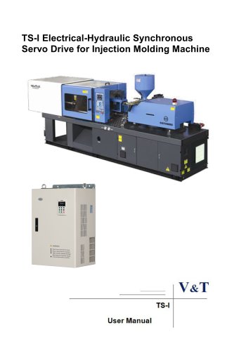
- VTdrive VY-JY Cabinet Type Injection Molding Machine Variable Frequency Drive(VFD) Manual

VTdrive VY-JY Cabinet Type Injection Molding Machine Variable Frequency Drive(VFD) Manual

VTdrive VY-JY Cabinet Type Injection Molding Machine Variable Frequency Drive(VFD) Manual
The V5-JY series by Shenzhen VTdrive Technology Co., Ltd. is a high-performance vector control asynchronous servo drive designed for the injection molding machine industry. It features advanced speed sensorless vector control technology, enhancing reliability and adaptability for the Chinese market.
- Control Modes: Two vector control modes with high startup torque and precise speed stabilization.
- Speed Sensorless Vector Control: Quick response and stable operation for various equipment.
- Tripless Operation: Robust current and voltage control for stable operation under varying loads.
- Low Frequency Operation: Large torque and stable operation at low frequencies.
- Instantaneous Mains Failure Reaction: Maintains operation during power failures with automatic restart.
- Speed Tracing Function: Smooth motor speed tracing without special hardware.
- Quick DC Braking: Efficient braking within 0.3s for industrial applications.
- International Standards Compliance: Meets IEC and UL standards for safety and electromagnetic compatibility.
- Integrated Design: Built-in braking units and expansion cards for specific applications.
- Adaptability: Compact design with comprehensive system protection and wide voltage range capabilities.
- Flexible Frequency Reference Modes: Multiple modes for operation and communication, including Modbus protocol.
- Host Computer Communication: Supports parameter upload/download and master-slave communication among drives.
- Customizable Functions: Users can define function codes and perform secondary development for process control.
- Usage Restrictions: Designed for three-phase motors only, not suitable for single-phase motors or safety-critical applications.
- Installation and Wiring: Must be performed by qualified personnel with proper grounding and adherence to safety standards.
The document provides a comprehensive guide on the V5-JY Asynchronous Servo Drive, focusing on its application in injection molding machines. It outlines the working principle, advantages, technical features, and operational guidelines for the servo drive.
The V5-JY Asynchronous Servo Drive is designed for energy-saving applications in injection molding machines. It features easy installation without altering the original equipment's control mode, oil, or circuit structure. The drive supports a wide range of torque output and ensures stable operation with advanced vector control features.
Key operational guidelines include:
- Ensure power supply phases and rated voltage match the nameplate to avoid damage.
- Avoid connecting the drive's output to capacitors or noise filters with phase lead.
- Do not perform dielectric strength tests on the drive.
- Separate main circuit and control circuit wires to prevent signal interference.
- Use appropriate cable lengths and output reactors to prevent overcurrent issues.
Safety measures include:
- Do not touch live terminals to avoid electric shock.
- Ensure isolation measures are in place when using auto failure reset functions.
- Do not start or stop the drive by switching the power supply directly.
- Handle high-temperature components like heatsinks and braking resistors with care.
Maintenance should be performed by qualified electricians, ensuring power is disconnected and residual voltage is discharged before inspection. Avoid touching circuit boards to prevent electrostatic damage.
The drive offers:
- High power factor output and reduced reactive power loss.
- Fast speed control and high starting torque.
- Customizable technology curves for different mold processes.
- Advanced power modules to minimize interference with control circuits.
The drive supports programmable logic and math operations, allowing for flexible control of frequency output based on digital and analog inputs. It includes features for logic operations and mathematical calculations to optimize performance.
The V5-JY Asynchronous Servo Drive is a cost-effective solution for enhancing energy efficiency in injection molding machines, offering significant power savings and maintaining operational reliability.
Avoid installing the product in environments with oil mist, metal powder, dust, hazardous gases, corrosive, combustible, or explosive substances. Do not install in salty areas, direct sunlight, or on combustible materials like wood. Ensure no drilling scraps enter the Asynchronous servo drive during installation.
The Asynchronous servo drive must be mounted vertically to maintain cooling efficiency, with adequate space as illustrated in the manual.
After wiring, close the door by following the specified directions to ensure it is securely latched.
Connection of Product and Peripheral Devices
Includes a connection diagram with components like power supply, contactor, AC/DC reactors, grounding, circuit breakers, noise filters, and braking resistors.
- Circuit Breaker: Capacity should be 1.5 to 2 times the rated current. Consider time features for overload protection.
- Leakage Circuit Breaker: Use a special breaker due to high-frequency leakage current, recommended B type with 300mA setting.
- Contactor: Limit operation to 10 times/min to prevent failure. Use thermal protection relay with braking resistor.
- AC/DC Reactors: Install if power supply capacity exceeds 600kVA or if voltage imbalance exceeds 3%.
- Noise Filters: Reduce noise input and output.
- Thermal Protection Relay: Required for multiple motors to prevent overtemperature.
- Output AC Reactor: Suggested for cables longer than 100m to prevent damage.
Specifications for circuit breakers, contactors, and wiring for different models are provided, including tightening torque and wire specifications.
Details the terminal symbols and their functions for different models, including input/output terminals and grounding.
- Power Supply Wiring: Ensure correct connection to prevent damage.
- Motor Wiring: Avoid short circuits and ensure proper connection to prevent damage and electric shock.
- Grounding Wiring: Ensure proper grounding to prevent leakage current issues.
- Interference Countermeasures: Use noise filters and proper cable routing to minimize interference.
Includes a diagram and description of control circuit terminals, detailing their functions and technical specifications.
Details on digital and analog input/output terminals, relay outputs, and their specifications, including voltage, current, and wiring modes.
- Ensure the short circuit plate between terminal +24V and terminal PLC is removed when using external power supply. Connect the short circuit plate between PLC and COM terminals.
- For NPN sink current wiring mode, remove the short circuit plate between terminal +24V and terminal PLC.
- For PNP draw-off current wiring mode, ensure correct polarity of external diode if Y1 or Y2 terminal is damaged.
- Includes user controller, relay, and grounding of the shielding cable.
- Terminal screw tightening torque is 0.5~0.6 N·m with a wire specification of 0.75 mm².
- AI1 and AO1 default to voltage input/output (0~10V), AI2 and AO2 default to current input/output (0~20mA).
- 485 terminal resistor selection is off by default.
- Indicators show frequency, current, voltage, rotating speed, and status with specific color codes.
- Keys include programming, escape, increase/decrease, shift, run, stop/reset, multi-function, and forward/reverse keys with specific functions.
- Two-level menu structure with basic, fast, non-leave-factory value, and last changed function codes menus.
- Basic menu includes all function codes; fast menu includes common codes for quick setup.
- Various symbols indicate status such as power on, DC braking, auto tuning, and menu modes.
The document is a user manual for the V5-JY series Asynchronous Servo Drive, detailing its operation panel, communication, and parameter settings. The operation panel is identified as a key type, and there is a noted issue with the LInE communication of the operation panel.
The manual provides a table for identifying symbols displayed via LED, correlating LED characters with their meanings, such as '0' for 'A', '1' for 'b', etc.
The manual outlines procedures for setting, verifying, and clearing passwords. Passwords are set by entering the function code twice, verified by entering the correct password, and cleared by setting the code to '0000' twice. Password protection can be enabled through key combinations or inactivity.
Keys can be locked to prevent unauthorized use. The locking function can be set to lock all keys, all except the multi-function key, or all except the RUN and STOP/RST keys. Unlocking is done via a specific key combination.
The operation panel has eight display statuses, including stopping parameters, running parameters, fault and alarm status, and menu navigation. The manual describes how to navigate these statuses and the auto-switching behavior after inactivity.
The manual includes a comprehensive list of function codes, detailing their factory settings, setting ranges, units, and properties. Key parameters include user password, function code protection, control operation mode, and frequency settings.
Guidelines for running the servo drive for the first time are provided, including fault handling and auto-tuning procedures. The manual advises on selecting auto-tuning based on motor load conditions.
The document provides a detailed parameter table, explaining each function code's meaning, factory settings, setting ranges, and properties. This includes basic function parameters, main and auxiliary reference parameters, key and display parameters, and start/stop parameters.
PA.17 to PA.19 describe settings for fault shielding and alarm attributes. Each setting allows for three options: 0 (fault not shielded, stopped upon fault), 1 (fault not shielded, non-stop upon fault), and 2 (fault shielded, no alarm and no stop). Specific faults are indicated by LED positions, such as EEPROM error, relay contact failure, and communication failures.
PA.20 and PA.21 cover fault locking and automatic reset functions. Faults can be locked (1) or not (0), and automatic reset can occur up to 20 times with intervals between 2.0 to 20.0 seconds.
Group Pb includes parameters for hopping frequency limits and digital regulating frequency control. These settings define frequency limits and actions upon power off or stopping, with options for integral functions.
Group PC outlines communication settings such as baud rate, data format, and master-slave modes. Baud rates range from 4800 to 57600 bps, and data formats include options for parity.
Group Pd details vector control settings, including speed/torque control, speed loop gains, and torque limits. These parameters are crucial for optimizing motor performance and ensuring safe operation.
Group d0 and d1 provide records of fault types, bus voltage, and operation times, as well as product identity information like serial numbers and software versions.
Group d2 and A0 cover display settings and user-defined function codes. These parameters allow customization of display information and protection of sensitive settings with passwords.
Chapter 6 describes basic function parameters, including password protection and function code display modes. Users can set passwords to protect parameters and choose between different display modes for efficiency.
- Analog Value Feedback Process Close Loop Control: Suitable for general speed control precision, utilizing analog feedback for parameters like temperature and pressure. Key settings are found in P1.02~P1.07 and Group P8.
- Single-phase Pulse Feedback Process Close Loop Control: Offers higher speed control precision with a pulse encoder installed at the motor or equipment axle end. Configuration involves setting the X7/DI terminal for single-phase pulse input (P5.06=47).
- Composite Control: Combines open loop and analog feedback closed loop control for specialized applications, allowing fine-tuning of physical parameters beyond open loop settings.
- Process Open Loop Control: High performance applications with precise rotation speed and torque, eliminating the need for a pulse encoder.
- Frequency and Voltage: Maximum output frequency (P0.11) and voltage (P0.12) are defined, with user-set upper (P0.13) and lower (P0.14) frequency limits based on process requirements.
- Acceleration/Deceleration: Parameters P0.08 and P0.09 define the time for acceleration and deceleration, with optional S curve time (P0.10) for smoother transitions.
- Torque Boost: Enhances low-frequency operation by increasing output voltage to ensure sufficient torque, adjustable based on load conditions (P0.16).
- Main and Auxiliary References: In open loop control, main and auxiliary references can be combined using various calculations (add, subtract, max, min) as defined in P1.01.
- Analog Feedback Close Loop Control: Allows for main and auxiliary reference and feedback calculations, with settings detailed in P1.02 to P1.07.
- Composite Operation: Combines open and closed loop references, with the closed loop adjustment result added or subtracted from the open loop reference (P1.08).
- Operation Panel Mode: Manual control via panel buttons for run, stop, and direction commands.
- Terminal Mode: Control through multifunctional terminals X1~X7, with settings in P5.00~P5.06.
- Host Computer Mode: Communication-based control using Modbus protocol.
This section describes the key-lock function on the operation panel to prevent mis-operation. The keys can be fully locked, partially locked, or fully unlocked. The multi-functional key can be customized for frequent operations, such as jog functions, emergency shutdowns, and switching display modes. Parameters P2.00 to P2.07 define these settings, including display benchmarks and coefficients for running and stopping statuses.
Different startup and stop modes are available for the Asynchronous Servo Drive. Startup modes include starting from a set frequency, DC magnetizing, and flying startup. Stop modes include deceleration, coasting, and DC braking. Parameters P3.00 to P3.13 cover settings for startup frequency, DC injection, and jog operations.
This section outlines the V/F curve settings for vector control mode, applicable to constant and variable torque loads. Users can define custom curves or select predefined power curves. Parameters P4.00 to P4.36 allow for setting multi-section digital voltage references and frequencies, which can be prioritized based on terminal status.
- Reference Frequency: Curves 1 and 2 are used to establish the relationship between analog values and setup frequency. Curves 3 and 4 convert external analog inputs into internal values.
- Analog Input Curves: Parameters P6.01 to P6.20 define input points and corresponding frequencies for curves 1 to 4, allowing for precise frequency setup based on input analog values.
- Analog Value Selection: Determined by P6.21, which selects functions for AI1, AI2, AI3, and DI terminals.
- Filtering Time: Parameters P6.22 to P6.24 allow adjustment of AI filtering time to improve anti-interference capability.
- Digital Signal Output: Y1 and relay terminals can output various signals such as running status, frequency arrival, and overload warnings.
- Analog Value Output: AO1 and AO2 terminals can output analog values with selectable ranges via jumpers.
- Pulse Output: Y2 terminal can output high-speed pulses up to 50kHz.
- Analog Output Calibration: Parameters P7.05 to P7.09 allow for gain and bias adjustments of AO outputs, affecting the output characteristics curves.
- Frequency and Current Detection: Parameters P7.18 and P7.19 are used for zero current detection and frequency arrival detection, respectively.
- Ensure different analog channels have distinct functions to avoid conflicts.
- Adjust filtering time based on the level of interference in the application environment.
The manual describes the function of detecting output frequency within a set range using Frequency Arrival Signal (FAR) and Frequency Level Detection Signal (FDT). Parameters such as FDT1 and FDT2 levels are adjustable between 0.00 to 300.00 Hz.
The document explains the configuration of multifunctional input and output terminals, which can be set as real or virtual. The status of these terminals is controlled by the host computer, independent of their physical state.
The PID control parameters include proportional gain (Kp), integral gain (Ki), and differential gain (Kd), which affect system response and stability. The manual provides guidelines for setting these parameters to avoid oscillations and ensure precise control.
Motor parameters such as load type, number of poles, rated velocity, power, and current are crucial for the servo drive's operation. The manual details an auto-tuning process to optimize these parameters, ensuring they match the motor's specifications.
The document outlines motor overload protection modes, including current mode and sensor mode, to prevent motor damage. It also discusses the importance of setting appropriate protection thresholds and overload protection times.
Figures such as the PID schematic diagram and motor overload protection characteristics curve provide visual guidance on parameter settings and system behavior.
The document outlines procedures for controlling motor speed using slip compensation. Adjustments are necessary when motor speed deviates from the target value. If the speed is below the target, increase the vector control slip compensation gain; if above, decrease it. Temperature changes affect motor parameters, necessitating adjustments to compensate for increased slip.
Several parameters are defined for optimal motor performance:
- Pd.15: Current loop scale coefficient (0~2000)
- Pd.16: Current loop integral coefficient (0~6000)
- Pd.17: Vector control slip compensation gain (electric) (10.0~300.0%)
- Pd.18: Vector control slip compensation gain (power generation) (10.0~300.0%)
The servo drive records fault codes, bus voltage, output current, and operation frequency during failures. It also logs total power-up and operation time, maximum temperature of the heat-sink, and bus voltage fluctuations.
Each servo drive has a unique serial number and software version identifiers. Display parameters include input status and failure sources for analog inputs and current detection.
Function codes can be customized and protected with a password. Displayed/hidden zones can be reset to factory defaults.
The document describes methods for setting the frequency in energy-saving modes for injection molding machines. Different user-defined methods can be selected based on the environment or mold requirements. Parameters for flow and pressure signal filtering are provided to enhance anti-jamming capabilities.
Settings for frequency curves are detailed, allowing for adjustments based on external input signals. These settings help determine the frequency components corresponding to flow and pressure signals.
The document outlines various function codes and parameters for the V5-JY Asynchronous Servo Drive, focusing on frequency curves, input points, and volume correspondence. It details the settings for different groups of frequency curves and the overlay permit function, which allows for frequency adjustments based on multi-speed selection.
- H0.23 to H0.32: These codes relate to the injection machine's frequency curve inputs and their corresponding per unit volumes, with values ranging from 0.0 to 100.0.
- H0.33: Overlay permit function, allowing frequency adjustments through multi-speed selection.
- H0.34: AI1/AI2 extension input permit, enabling the use of expansion card inputs.
- H0.35 to H0.40: Various settings for frequency parameters, motor current, and voltage hysteresis for motor heat protection.
The document describes the logic operations for digital terminals, including AND, OR, and NON-operations. It explains how to set logical relationships and priorities among digital inputs to achieve desired outputs.
Analog inputs can undergo mathematical operations to produce results used for frequency settings. The document details how to configure these operations, including inversion and operator priority settings.
Chapter 7 provides a list of fault and alarm information for the servo drive, including overcurrent and overvoltage protection during various operations. It offers potential causes and solutions for each fault, such as checking input power supply, adjusting motor parameters, and replacing the servo drive with a proper model if necessary.
- Ensure proper setting of motor parameters to avoid faults.
- Adjust acceleration and deceleration times to prevent overcurrent protection.
- Use appropriate energy braking components for large inertial loads.
- Regularly check input power supply and motor wiring to prevent overvoltage issues.
- Failure Codes and Descriptions: The document lists numerous failure codes such as E.oV2 (Over voltage protection), E.PCU (Interference protection), and E.AUt (Auto-tuning failure), among others. Each code is associated with specific failure descriptions and potential causes.
- Potential Causes: Causes range from motor short circuits, abnormal input power supply, loose connections, to environmental factors like ambient over-temperature.
- Solutions: Solutions include checking motor wiring, adjusting deceleration time, seeking technical support, and replacing faulty components.
- Routine Maintenance: Regular checks are recommended for operating environment conditions such as temperature, humidity, and dust levels. The document advises using specific instruments like thermometers and humidiometers for accurate assessments.
- Periodic Maintenance: Conducted every three to six months, this involves inspecting main circuit terminals, PE terminals, and control circuit terminals to ensure all connections are firm and reliable.
- Component Replacement: The document highlights the importance of replacing vulnerable components like cooling fans and electrolytic capacitors, which are prone to wear and damage over time.
- Only trained personnel should perform maintenance and component replacement to avoid risks of electric shock.
- Ensure the power supply is shut down for at least ten minutes before inspection.
- Maintain a clean environment free of dust, oil, and foreign objects to prevent equipment damage.
- Function 0x03: Reads parameters and status words.
- Function 0x06 (0x41): Rewrites single function codes or control parameters.
- Function 0x10 (0x42): Rewrites multiple function codes.
- Function 0x17: Reads and writes multiple function codes.
- Connecting one asynchronous servo drive to the computer is illustrated in Figure 3.
- Connecting multiple asynchronous servo drives to the computer is illustrated in Figure 4.
- Auto-tuning Process: Set parameters such as P0.01=5, rated voltage (P0.12), basic frequency (P0.15), upper frequency limit (P0.13), max frequency (P0.11), and motor parameters (P9.00–P9.04). Set P9.15=2 and press RUN to perform tuning. Ensure disconnection from the load initially.
- Open Loop Setting Process: Detailed steps are provided in the manual.
- Closed Loop Setting Process: Detailed steps are provided in the manual.
- Composite Control Setting Process: Detailed steps are provided in the manual.
- Vector Control 2 Issues: Check power class differences, parameter auto-tuning, and control line connections.
- Vector Control 1 Issues: Ensure parameter auto-tuning and check control line connections.
- Reverse Operation Frequency Issue: Verify frequency settings and function code P3.09.
- Braking Resistor Issue: Check connections and parameter PA.09.
- Analog Input/Output Deviations: Ensure proper jumper settings and calibrate using function codes P6.00-P6.2 and P7.05-P7.09.
- Analog Input Error E.AIF: Check jumper settings, input voltage, and resistance values.
- Error E.P10: Verify voltage and resistance values.
- 485-based Communication Issues: Ensure data format consistency, address settings, and proper wiring.
- Parameter Copying Issues: Ensure compatibility and proper power cycling.
- Keyboard Display Issues: Check connections and signal correspondence.
- Function Code Modification Issues: Verify settings and encryption status.
- Motor Rotation Direction Change: Use operation panel controls or terminal settings.
- Fan Operation on Power Up: Depends on power class and temperature control.
- CN1 Busbar Issues: Loose or damaged busbar can cause errors and prevent operation.
Catalog excerpts

V5-JY Cabinet Type Injection Molding Machine Variable Frequency Drive
Open the catalog to page 1
The V5-JY series is a high-performance vector control asynchronous servo drives provided by Shenzhen VTdrive Technology Co., Ltd. This frequency inverter is special for injection molding machine industry .The product adopts the most advanced international technology fully synchronized speed sensorless vector control technology, not only has the same excellent control performance and international high-end ac drives, but also combined with the application characteristics of the injection molding machine in China, to further strengthen the reliability of the product and the environment adaptability...
Open the catalog to page 2
Excellent Performance Control Mode Vector Control 1 Offering excellent vector control performance and insensitive to motor parameters. Startup torque: 0.50Hz Speed adjustment range: 1:100 Speed stabilization precision: ± 0.5% The motor could stable operating with 150% rated torque, 0.5HZ Vector Control 2 Precise speed sensorless vector control technology realizes AC motor decoupling, enabling the DC motorization of operation control. Startup torque: 0.25Hz Speed adjustment range: 1:200 Speed stabilization precision: ± 0.2% Excellent Control Performance under Speed Sensorless Vector Control Mode...
Open the catalog to page 3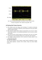
Fig. 1 Quick acceleration/deceleration four-quadrant running in the form of 0Hz →Forward running 50Hz→0Hz→Reverse running 50Hz→0Hz Realizing Real Tripless Operation With excellent current and voltage control technology, 0.1s repetitive and alternate acceleration and deceleration is performed, and the Asynchronous servo drive realizes stable and tripless operation. With extremely powerful loading capacity, the Asynchronous servo drive can realize stable tripless operation in any acceleration/deceleration time and under any impact load condition. With strong short-time overload capacity, the Asynchronous...
Open the catalog to page 4
Fig. 2 The Asynchronous servo drive realizes stable control of current and voltage and will not trigger under any acceleration/deceleration condition as well as stable operation condition Large Torque and Stable Operation at Low Frequency under Vector Control With precise speed identification and rotor magnetic flux orientation, the torque responds quickly and stable operation in the case of 0.25Hz load mutation. Startup torque: Open loop vector control: 0.25Hz; 180% rated torque Speed stabilization precision: Open loop vector control: ±0.2% It is especially suitable for: Medium and large wire-drawing...
Open the catalog to page 5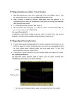
Unique Instantaneous Mains Failure Reaction Upon the instantaneous mains failure, the energy of the motor feedback bus will keep the Asynchronous servo drive running till the mains resumes normal. When shutdown is caused by long-term power-failure during the operation of the Asynchronous servo drive, the Asynchronous servo drive will provide alarm message after power resumes normal. It supports the automatic operation after power-up. The deceleration time during the power failure and the acceleration time after the power recovery can be set independently. It is especially suitable for: Instantaneous...
Open the catalog to page 6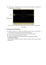
♦ Tracing mode 2: Impactlessly pull down the motor from high-speed to low speed and then accelerate to normal speed. Rotating speed p Coupling I BW Limit | Vernier I Invert 1 Probe Fig. 5 Tracing and smooth startup after frequency reduction upon the motor high-speed free rotation ■ Unique Quick DC Braking ♦ Within the range of 0 to 300Hz, the Asynchronous servo drive can realize back electromotive force elimination and quick DC braking within 0.3s. ♦ DC current input in the most efficient way to improve the braking capacity. ♦ There is no initial waiting time for the DC braking. ♦ Special function...
Open the catalog to page 7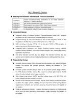
High Reliability Design Meeting the Relevant International Product Standards IEC61800-2 General requirements–Rating specifications for low voltage adjustable frequency a.c. power drive systems EMC product standard including specific test methods Electromagnetic compatibility (EMC) –Part6: Generic standards Safety requirements –Electrical, thermal and energy UL Standard for Safety for Power Conversion Equipment Integrated Design Integrated design of software protocol: Terminal/operation panel 485, universal expansion port SPI protocols are integrated (Modbus protocol). Integrated design of main...
Open the catalog to page 8
Comprehensive system protection function: software/hardware current limiting protection, overcurrent and overvoltage protection, grounding short circuit protection, overload protection, IGBT short circuit protection, abnormal current detection protection, abnormal relay contact protection. Perfect terminal protection function: short circuit and overload protection for the +24V and +10V power supply of the control terminal, operation panel cable reverse connection protection, input signal cable disconnection and abnormal analog input protection. Over-temperature prealarm protection function: Automatic...
Open the catalog to page 9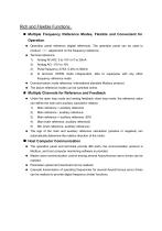
Rich and Flexible Functions Multiple Frequency Reference Modes, Flexible and Convenient for Operation Operation panel reference (digital reference). The operation panel can be used to conduct ∨/∧ adjustment on the frequency reference. Terminal reference: Xi terminal: UP/DN mode independent, able to superpose with any other frequency reference mode Communication mode reference: International standard Modbus protocol. The above reference modes can be switched online. Multiple Channels for Reference and Feedback Under the open loop mode and analog feedback close loop mode, the reference value can...
Open the catalog to page 10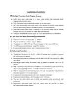
Customized Functions ■ Multiple Function Code Display Modes ♦ bASE: Basic menu mode (refer to 5.1 basic menu function code parameter table), displays all the function codes. ♦ FASt: Fast menu mode, is especially suitable for the naive users. ♦ ndFt: Non-leave-factory value menu mode, it only displays the function codes different from the leave-factory values to facilitate the inquiry and commissioning. ♦ LASt: Last change menu mode, it displays the 10 functions codes that are recently changed and P0.02 to facilitate the inquiry and commissioning. ♦ The users can define the function codes for...
Open the catalog to page 11All VTDRIVssE Technology Limited catalogs and technical brochures
 VS5 Solar pump inverter
3 Pages
 VTdrive What is a Choke Coil
2 Pages














- Electronic filter
- Passive electronic filter
- AC electronic filter
- Wire-wound resistor
- Solar DC/AC inverter
- 3-phase AC drive
- Three-phase electronic filter
- 3-phase frequency converter
- Choke coil
- Three-phase DC/AC inverter
- DC/AC inverter for industrial applications
- Band-pass electronic filter
- EMI filter
- Housed resistor
- Compact frequency inverter
- IP20 frequency inverter
- Digital output frequency inverter
- Motor frequency converter