
- Catalogs
- VTDRIVssE Technology Limited
- VTdrive TS-I Electrical-Hydraulic Synchronous Servo Drive for Injection Molding Machine Manual

VTdrive TS-I Electrical-Hydraulic Synchronous Servo Drive for Injection Molding Machine Manual
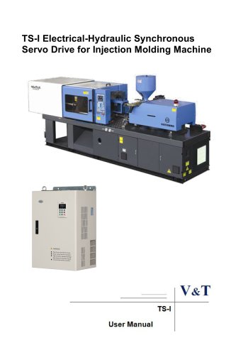
VTdrive TS-I Electrical-Hydraulic Synchronous Servo Drive for Injection Molding Machine Manual
- Product Model Description: Information on the drive series, power supply class, power class, and software/hardware versions.
- Technical Parameters: Lists various models with specifications like input voltage, power supply capacity, input/output current, and overload capacity.
- Product Components: Includes components like dust guard, mounting hole, cooling fan, operation panel, and heatsink.
- Mounting Dimensions: Detailed dimensions and weights for different models.
- Braking Resistor Models: Specifications for braking units and resistors.
- Installation Environment: Guidelines for installation sites, avoiding oil mist, metal powder, hazardous gases, and ensuring proper ventilation.
- Mounting Direction and Space: Instructions for vertical mounting and maintaining clearance for cooling.
- Operation Panel and Cover Removal/Mounting: Step-by-step instructions for removing and mounting operation panels and covers.
- Connection of Drive and Peripheral Devices: Diagram and description of connections including power supply, contactor, input AC reactor, and grounding.
- Operation Panel Introduction: Overview of the operation panel and its indicators.
- Menu Style and Password Operation: Details on navigating the menu and using password protection.
- Running for the First Time: Instructions for initial operation and commissioning of the servo pump.
- Basic Menu Function Codes: A list of function codes for configuring the servo drive.
- Multifunctional Terminal Definitions: Definitions for multifunctional terminals and relay outputs.
- Faults and Solutions: Common faults and troubleshooting procedures.
- Debugging Process: Answers to common questions during debugging.
- Component Selection: Method for selecting main components for the injection molding machine electrolytic mixing system.
- RCCB Installation: Use a B type RCCB with a leakage current setting of 300mA.
- Contactor Usage: Limit contactor tripping to a maximum of 10 times per minute.
- Braking Resistor: Install a thermal protection relay to prevent overheating damage.
- Input Reactors: Use AC or DC reactors if the power supply capacity exceeds 600kVA.
- Noise Filters: Install input and output noise filters to reduce interference.
- Thermal Protection: Use thermal protection relays when one drive controls multiple motors.
- Output AC Reactor: Recommended for cable lengths over 100m.
- Power Supply Wiring: Ensure correct phase and voltage matching with the drive's nameplate.
- Motor Wiring: Avoid short circuits and ensure proper grounding.
- Grounding: Grounding resistance should be less than 10 ohms.
- Interference Countermeasures: Use short connections for noise filters and shielded cables for signal wires.
- Jumper Function Description: Functions of various jumpers on the control panel.
- Installation Cautions: Guidelines for installing the servo motor and pressure sensor.
- Operation Panel and Indicators: Includes various indicators and buttons for controlling and monitoring the servo drive.
- Menu Structure: Organized into a two-level structure with various groups and function codes.
- Menu Modes: Different menu modes are available for various operations.
- Password and Key Operations: Password protection and key locking features are available to secure settings.
- Operation Panel Display: The operation panel can display various statuses, including stopping and running parameters, fault and alarm statuses, and menu navigation.
- DC Bus Voltage: The DC bus voltage is displayed as 543V during stop.
- Factory Settings Restoration: Parameters in the P area can be restored to factory settings using P0.01=3, excluding motor parameters (F9 group).
- Frequency and Password Settings: Frequency can be set using P0.05=25.00Hz. User passwords can be set and verified.
- First-Time Running: Includes setting motor parameters, analog calibration, and test running the injection molding machine.
- Motor Tuning: Set motor parameters according to the motor nameplate and perform tuning.
- Running Direction Confirmation: Set P0.05=20rpm to check motor direction and adjust if necessary.
- Servo Pump Configuration: Set oil pressure control mode and command channels.
- Pressure Flow Marking: Set max output pressure and flow.
- PID Control for Oil Pressure: Adjust PID parameters to stabilize pressure.
- Function Code Parameters: Detailed list of function codes, their meanings, factory settings, and setting ranges.
- Analog Reference Parameters: Configuration for AI1 to AI3 and DI analog value input curves.
- AI Parameters: Defines minimum voltage values for AI1, AI2, and AI3 inputs.
- Multi-function Output: Includes settings for Y1, Y2/DO, Relay 1, Relay 2, AO1, and AO2 terminals.
- Gain and Bias: Configurations for AO1 and AO2 gain and bias.
- Plunger Pump: Settings for single or dual pump types.
- Multi Pump Control: Parameters for pump merging, splitting, and control modes.
- Motor Specifications: Details on motor type, poles, rated velocity, power, current, voltage, and torque.
- Inductance and Resistance: Parameters for Q and D axis inductors, stator resistance, and rotor resistance.
- Carrier Frequency: Settings for frequency and automatic adjustment options.
- Overload Alarms: Configurations for motor overload detection levels and times.
- Fault Masking: Options for masking and alarm settings for various fault types.
- Speed Oscillation Limits: Defines low and high limits to avoid speed oscillations.
- Parameter Copy: Functions for uploading and downloading parameters.
- Baud Rate and Data Format: Settings for communication speed and data format.
- Output Torque: Maximum and minimum output torque settings.
- Fault Records: Logs of fault types, bus voltage, and current during faults.
- Software and Serial Numbers: Information on software versions and manufacturing barcodes.
- Temperature and Voltage: Displays for heatsink temperature and reference voltages.
- Adjustment Coefficients: Coefficients for reference pressure and flow adjustments.
- Terminal X: Definitions for functions such as communication enable, fault reset, and motor temperature input.
- Relay and Y Terminal: Definitions for outputs like servo running signals and cooling fan control.
- Analog Value A0 Output: Defines the multifunction analog value A0 output.
- Faults and Solutions: Lists various failure codes, descriptions, potential causes, and solutions.
- Guidance on addressing common issues during the debugging process.
- Common Questions: Addresses frequently asked questions during the debugging process.
Catalog excerpts

TS-I Electrical-Hydraulic Synchronous Servo Drive for Injection Molding Machine
Open the catalog to page 1
Foreword TS−I series synchronous servo drive is a high performance and highly reliable servo drive with high responding speed for electrolytic mixing system of the injection molding machine. The product is based on a flexible digital control module that uses high performance DSP, which realizes high performance vector control, precision position and speed control, non-linear weak magnetic high speed control and position calibration space vector low speed control for each kind of control algorithm and software for servo motors. In the meantime, in order to meet the high speed and high precision...
Open the catalog to page 3
High Reliability Design □ Meeting the Relevant International Product Standards IEC61800−2 IEC61800−3 IEC61000−6 IEC61800−5−1 UL508C General requirements–Rating specifications for low voltage adjustable frequency a.c. power drive systems EMC product standard including specific test methods Electromagnetic compatibilityEMC–Part6:Generic standards Safety requirements –Electrical, thermal and energy UL Standard for Safety for Power Conversion Equipment Unified design of hardware interfaces: Unified design of control board, button/shuttle type operation panel facilitates the operation and maintenance....
Open the catalog to page 4
Independent power supply for control: The drive provides an independent DC input interface. External UPS power supply can be connected to the drive through an option card. It is applicable to the applications of oilfield, chemical industry and printing and dyeing industry. Power-up self-detection function: It realizes the power-up detection on the peripheral circuit, such as motor grounding, disconnection, greatly improving the system reliability. Comprehensive system protection function: software/hardware current limiting protection, overcurrent and overvoltage protection, grounding short circuit...
Open the catalog to page 5
Customized Functions □ Multiple Function Code Display Modes X bASE: Basic menu mode, displays all the function codes. FASt : Fast menu mode,display the common parameters to be used in the commissioningis especially suitable for the naive users. ndFt: Non-factory setting menu mode, it only displays the function codes different from the leave-factory values to facilitate the inquiry and commissioning. LASt: Last change menu mode, it displays the 10 functions codes that are recently changed and P0.02 to facilitate the inquiry and commissioning. User can define the function codes for inquiry and...
Open the catalog to page 6
Safety Precautions Description of safety marks: Danger: The misuse may cause fire, severe injury, even death. Note: The misuse may cause medium or minor injury and equipment damage. This series synchronous servo drive is used to control the 3-phase (single phase) permanent magnetic synchronous motor (PMSM), cannot be used for single-phase motor or other applications. Otherwise, drive failure or fire may happen. This series of drive cannot be simply used in the applications directly related to the human safety, such as the medical equipment. This series of drive is produced under strict quality...
Open the catalog to page 7
Wiring Danger The wiring must be conducted by qualified electricians. Otherwise, electric shock may happen or drive damage. Before wiring, confirm that the power supply is disconnected. Otherwise, electric shock may happen or fire. The PE terminal must be reliably grounded, and should use the third grounding method for grounding the PMSM motor at equal voltage potential, otherwise, the drive enclosure may become live. Please do not touch the main circuit terminals. The wires of the main circuit terminals must not contact the drive enclosure. Otherwise, electric shock may happen. The connecting...
Open the catalog to page 8
Operation Danger Power supply can only be connected after the wiring is completed and the cover is installed. It is forbidden to remove the cover in live condition; otherwise, electric shock may happen. When auto failure reset function or restart function is enabled, isolation measures shall be taken for the mechanical equipment, otherwise, personal injury may be caused. When the drive is powered on, its terminals are still live even when it is in stop state. Do not touch the drive terminals; otherwise electric shock may happen. The failure and alarm signal can only be reset after the running...
Open the catalog to page 9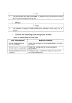
The circuit boards have large scale CMOS IC. Please do not touch the board to avoid the circuit board damage caused by ESD. Others Danger It is forbidden to modify the drive unauthorizedly; otherwise, human injury may be caused. Confirm the following when the goods arrives: Confirm the following when the goods arrive: Items to be confirmed Whether the goods are the drive you ordered? Check if the information in the nameplate is same with that in the order? Whether there is any damage? Check if the package and the unit are damaged in transportation? Whether the fasteners become loosened? If necessary,...
Open the catalog to page 10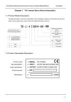
TS-I Electrical-Hydraulic Synchronous Servo Drive for Injection Molding Machine User Manual Chapter 1 TS-I series Servo Drive Introduction 1.1 Product Model Description The digits and letters in the drive model field on the nameplate indicate such information as the drive series, power supply class, power class and software/hardware versions. 1.2 Product Nameplate Description Product model Input specification Output specification Product barcode
Open the catalog to page 13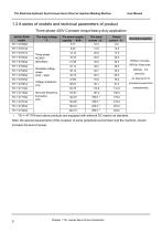
TS-I Electrical-Hydraulic Synchronous Servo Drive for Injection Molding Machine User Manual 1.3 A series of models and technical parameters of product Three-phase 400V Constant torque/heavy-duty application servo drive The power supply capacity KVA 5.77 Three-phase AC380V 50Hz/60Hz Allowable voltage range 323V528V Allow the frequency fluctuation ±5% minutes (inverse time Overload capacity TS−I−4T176A and above products are equipped with external DC reactor as standard. Note: the special requirements of the occasion of some peripheral environment and the machine, should increase the level of power....
Open the catalog to page 14All VTDRIVssE Technology Limited catalogs and technical brochures
 VS5 Solar pump inverter
3 Pages
 VTdrive What is a Choke Coil
2 Pages














Archived catalogs

- Electronic filter
- Passive electronic filter
- Frequency inverter
- Variable frequency drive
- AC electronic filter
- Wire-wound resistor
- Solar DC/AC inverter
- 3-phase AC drive
- Three-phase electronic filter
- 3-phase frequency converter
- Choke coil
- Three-phase DC/AC inverter
- DC/AC inverter for industrial applications
- Band-pass electronic filter
- EMI filter
- Housed resistor
- Compact frequency inverter
- IP20 frequency inverter
- Digital output frequency inverter
- Motor frequency converter