
- Catalogs
- VTDRIVssE Technology Limited
- VTdrive Frequency Converter V5-H-4T5.5G/7.5L Line Reactors

VTdrive Frequency Converter V5-H-4T5.5G/7.5L Line Reactors

VTdrive Frequency Converter V5-H-4T5.5G/7.5L Line Reactors
A line reactor is an electrical device used to filter high-frequency voltage transients, installed in series with an electrical load. It is commonly used to reduce harmonics and transient voltages on the line side of adjustable speed drives (ASDs). Line reactors are specified by voltage, power ratings, and percent impedance, which indicates the reduction in line voltage.
Transient Voltage Mitigation
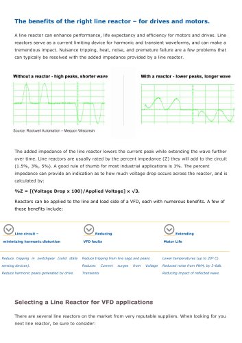
Voltage transients can occur due to utility capacitor bank switching or equipment switching, potentially causing an ASD's DC bus voltage to trip. Installing 3-5% line reactors can mitigate these transients, reducing or eliminating DC bus overcurrent trips.
Reduced Current Harmonics and Line Current
ASDs can increase current harmonics, which may interfere with electrical distribution systems and cause overheating of conductor insulation. Line reactors help attenuate current harmonics and reduce overall line current.
Considerations for Line Reactor Installation
1. Ensure the drive is at least 70% loaded, as lightly loaded drives will not benefit from line reactors.
2. Confirm the ASD can tolerate a reduction in steady-state line voltage based on the reactor's impedance.
3. Check if the ASD includes DC link reactors, which may suffice for mitigating voltage transients.
4. Be aware of potential resonant interactions between power factor correction capacitors and utility-switched capacitors, which can amplify voltage transients.
5. Consult an electrical engineer to evaluate the facility's specific needs for line reactors.
Catalog excerpts
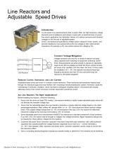
Line Reactors and Adjustable Speed Drives Introduction A Line reactor is an electrical device that is used to filter out high frequency voltage transients and is installed on each phase in series with an electrical load. A typical line reactor application (see illustration below) is to reduce harmonics and transient voltages on the line side of adjustable speed drives. Line reactors are specified by voltage, power ratings (in horse- power), and percent impedance. Line reactors reduce the line voltage by their rated percent impedance. For example, a 3% line reactor reduces the voltage by 3%. Transient Voltage Mitigation A1 Line Reactors Voltage transients can occur for a variety of reasons including utility capacitor bank switching or equipment switching. Sometimes, these transients are large enough to elevate an adjustable speed drive’s DC bus voltage such that the drive’s control circuitry will sense a trip condition and shut down the drive. In many cases, the installation of 3 – 5% line reactors may reduce these high frequency transients such that DC bus overcurrent trips are reduced or eliminated altogether. Reduced Current Harmonics and Line Current Adjustable speed drives are known to increase current harmonics. These harmonics are sometimes injected back through the electrical supply and may interfere with a building’s electrical distribution system. Harmonics cause the overheating of conductor insulation, which can lead to premature insulation failure. Line reactors will actually attenuate some of the current harmonics, and also reduce the overall line current. Are Line Reactors The Right Application? Before installing line reactors, check the following: 1. Assure that the drive is at least 70% loaded. Line reactors installed on lightly loaded adjustable speed drives will not alleviate the transient voltage trips. 2. Assure that the adjustable speed drive can tolerate a reduction in steady state line voltage based on the rated percentage impedance. Most utilities will operate within a + or – 5% band above and below nominal voltage levels. If the supply voltage swings down to –5% at some parts of the day, a 5% line reactor will effectively reduce the voltage at the drive input terminals by 10% of nominal. 3. Some adjustable speed drive manufacturers install DC link reactors as a standard component of their products. If so, then a 3% link reactor may be enough to mitigate line voltage transients. Higher impedance ratings may be required for drives without integral DC link reactors. 4. Customer site power factor correction capacitors may have a resonant tuned interaction with utility-switched capacitors that actually amplify the voltage transient magnitude by as much as 2 – 3 times. Generally a 10 – 20:1 ratio between utility capacitors and power factor correction capacitors are the range of concern for this resonance effect. 5. Have a consulting electrical engineer evaluate your specific facility to determine if line reactors can be beneficial. Shenzhen VTdrive Technology Co.,Ltd. Tel: +86-755-23060667 Website: www.vtdrive.com E-mail: [email protected]
Open the catalog to page 1All VTDRIVssE Technology Limited catalogs and technical brochures
 VS5 Solar pump inverter
3 Pages
 VTdrive What is a Choke Coil
2 Pages















Archived catalogs

- Electronic filter
- Passive electronic filter
- Frequency inverter
- Variable frequency drive
- AC electronic filter
- Wire-wound resistor
- Solar DC/AC inverter
- 3-phase AC drive
- Three-phase electronic filter
- 3-phase frequency converter
- Choke coil
- Three-phase DC/AC inverter
- DC/AC inverter for industrial applications
- Band-pass electronic filter
- EMI filter
- Housed resistor
- Compact frequency inverter
- IP20 frequency inverter
- Digital output frequency inverter
- Motor frequency converter