1. Catalogs
  2. VTDRIVssE Technology Limited
  3. VTdrive FIT-Closed Loop VFD for Industrial

VTdrive FIT-Closed Loop VFD for Industrial

VTdrive FIT-Closed Loop VFD for Industrial
1 / 276 PagesView full catalog

VTdrive FIT-Closed Loop VFD for Industrial

Product catalog summary
Preface: The FIT series Frequency Inverter is designed for controlling asynchronous and permanent magnet synchronous motors, suitable for industrial applications like spinning and automation. The manual provides guidance on product selection, parameter setting, operation, and maintenance.
Introduction: The FIT series improves on previous models with enhanced low-speed stability, motor protection features, and support for multiple encoders and customizable parameters.
Safety Information and Precautions: Emphasizes safety during installation and operation, advising on proper handling, grounding, and contacting customer service for failures.
Product Information: Details naming conventions, component identification, technical specifications, and system composition.
Mechanical and Electrical Installation: Provides guidelines for proper installation and integration into existing systems.
Operation Display and Applications: Introduces the operation interface, function code management, and control methods for starting and stopping the inverter.
Function Parameter List: Lists function parameters for basic functions, monitoring, and specific motor control settings.
EMC (Electro Magnetic Compatibility): Discusses EMC standards, installation guidelines, and interference mitigation measures.
Type Selection and Dimension: Includes electrical specifications, dimensions, and type selection for brake units and resistors.
Maintenance and Failure Diagnosis: Details maintenance procedures, failure alarms, and troubleshooting measures.
Appendices: Includes instructions for IO expansion cards, encoder expansion cards, and the FIT Modbus communication protocol.
Specifications: Key features include braking time range, JOG control, automatic voltage regulation, and torque limit and control.
Procedures: Provides installation and operation procedures, emphasizing environmental conditions and space requirements.
Standards and Recommendations: Advises on installation environments and avoiding capacitors or surge suppressors on the output side.
Peripheral Electrical Elements: Describes necessary elements for safe operation, including air switches and contactors.
Electrical Installation: Details main circuit terminal connections and emphasizes proper wiring.
Wiring Standards and Precautions: Covers input power, DC bus, brake resistance, and output side wiring standards.
Control Terminal Specifications: Details power supply terminals, analog and digital inputs, and digital outputs.
Operation and Display Interface: Describes panel functions, keyboard functions, and function code management.
Overview: The manual provides comprehensive instructions on configuring and operating the inverter, including quick scanning modes and frequency control.
Quick Scanning Modes: Offers user-defined and default value scanning modes for function codes.
Function Code Display Modes: Facilitates quick access and modification of function parameters.
Multifunctional Key (MF.K): Allows switching command sources or changing rotation direction.
State Parameter Consultation: Displays various state parameters in stop and running states.
Start and Stop Control: Supports various start and stop commands and modes.
Jog Operation: Supports low-speed testing or debugging.
Frequency Control: Offers multiple frequency reference channels and sources.
Frequency Source Determination: Describes methods for determining operation frequency.
Auxiliary Frequency Reference: Aligns with the main frequency source and can be set using function codes.
Run Command Switching and Frequency Reference Binding: Allows setting respective frequency sources for command sources.
Analog Frequency Source Usage: Describes analog input terminals and optional expansion cards.
Pulse Frequency Source Usage: Frequency can be given by terminal pulse signal.
PID Regulator Usage: Includes a built-in PID regulator for automatic process control.
Swing Work Mode: Used in textile processing to improve uniformity and density.
Multi-Speed Mode Setting: Allows setting up to 16-stage operation frequency.
Motor Operation Direction: Describes changing motor direction and reverse control.
Fixed Length Control Mode: Uses DI terminal to collect length pulse for control.
Counting Function Usage: Describes collecting count value and stopping when set value is reached.
Motor Parameter Setting and Automatic Tuning: Describes setting accurate motor parameters for vector control.
Specifications and Motor Parameters: Outlines rated power, voltage, current, and speed for multiple motors.
Motor Tuning Procedure: Describes tuning process for asynchronous motors.
Multi-Motor Parameter Switching: Supports switching between four motor parameter sets.
Digital Input (DI) Ports: Describes configuration and use of DI ports.
Digital Output (DO) Ports: Describes configuration and use of DO ports.
Analog Input (AI) and Output (AO) Ports: Supports multiple AI and AO ports for various signals.
Encoder and PG Port Usage: Describes use of encoders for closed-loop vector control.
Serial Communication: Supports RS485 communication using MODBUS-RTU protocol.
Expansion Card Interface: Describes available expansion cards for additional inputs and outputs.
Password and Parameter Management: Includes password protection and parameter memory functions.
Function Parameter List: Provides a detailed list of function parameters.
Specifications: Outlines set range and default values for function codes.
Procedures: Provides instructions on setting various parameters.
Norms and Standards: Adheres to standard practices for frequency inverters.
Recommendations: Advises on configuring inverter settings according to application requirements.
Key Data from Tables: Lists function codes, set ranges, default values, and changeability.
Critical Information: Highlights critical parameters for efficient operation.
Control Optimization (Group A5): Outlines parameters for optimizing control.
AI Curve Settings (Group A6): Provides settings for AI curve inputs.
AIAO Calibration (Group AC): Details calibration settings for AI and AO voltages and currents.
Monitoring Parameters (Group U0): Lists basic monitoring parameters.
Basic Functional Groups (Group F0): Describes basic functional settings.
Key Takeaways: Emphasizes selecting appropriate control modes and calibration settings.
Closed-loop Control: Describes use of closed-loop control systems.
Communication Reference: Explains frequency given via Modbus communication.
Auxiliary Frequency Source: Details selection and configuration of auxiliary frequency sources.
Frequency Source Superposition: Discusses parameters for frequency superposition.
Frequency Settings: Covers various frequency settings.
Carrier Frequency: Provides guidance on adjusting carrier frequency.
Acceleration/Deceleration Time: Describes settings for acceleration and deceleration times.
Motor Parameter Selection: Explains selecting motor parameters for driving multiple motors.
Critical Information: Advises on setting frequency sources and carrier frequency.
Specifications: Outlines parameters for motor type selection and tuning procedures.
Standards and Recommendations: Recommends tuning under keyboard operation mode.
Key Parameters: Highlights parameters for asynchronous and synchronous motors.
Encoder Settings: Provides guidance on setting encoder types and pulse counts.
Vector Control Parameters: Discusses parameters for vector control.
Torque Control: Explains setting torque upper limit.
Specifications: Outlines parameters for excitation and torque adjustment gains.
Procedures: Provides guidance on setting and adjusting parameters.
Recommendations: Includes recommendations for reducing PI gains and using automatic torque boost.
Norms and Limitations: Specifies default values and set ranges for parameters.
Key Data from Tables and Diagrams: Includes tables and diagrams for parameter settings.
Specifications and Settings: Describes output logic and AO1 output signal settings.
Start-Stop Control (Group F6): Details start and stop control modes and parameters.
Keyboard and Display (Group F7): Describes function selection and display settings.
Specifications: Outlines parameters for frequency inverter settings.
Procedures: Provides instructions for optimizing inverter performance.
Norms and Recommendations: Recommends setting parameters for safe operation.
Key Functions: Describes jog operation, hopping frequency, and protection settings.
Critical Information: Highlights importance of protection settings and avoiding resonance.
Diagrams and Figures: References diagrams illustrating operational functions.
Specifications: Describes calibration coefficient and motor overload protection settings.
Procedures: Outlines operational parameters and settings for frequency inverter.
Overspeed and Speed Deviation Tests: Describes parameters for overspeed and speed deviation tests.
PID Control Functionality: Describes process control method for maintaining stability.
PID Parameter Switching: Allows switching between two sets of PID parameters.
Feedback and Output Filtering: Manages feedback and output filtering times.
Swing Frequency and Fixed Length Control: Describes swing frequency functions and fixed length control.
Critical Parameters and Best Practices: Emphasizes setting appropriate values for tests and PID gains.
Specifications and Procedures: Describes use of multi-functional digital input terminal for gathering count values.
Multi-stage Instruction and Simple PLC Function: Supports multi-stage instructions for various applications.
Communication and Customization: Covers communication parameters and user customization of function codes.
Display and User Interface: Manages display attributes for function parameters.
User Customized Parameter Mode: Indicates user-modified parameters with a 'u' prefix.
User Changed Parameter Mode: Denotes user changes with a 'c' prefix.
FP-04 Function Code Modification: Prevents accidental changes to function parameters.
Group A0 - Torque Control Parameters: Describes torque control mode and settings.
Group A2 - Motor Parameters: Covers motor type selection and tuning settings.
Group A5 - Control Optimization Parameters: Describes control optimization settings.
Specifications and Settings: Describes random PWM and quick current limit settings.
AI Curve Settings: Describes AI curve settings and hooping function.
Calibration and Monitoring: Describes AI/AO calibration and monitoring parameters.
Specifications: Provides detailed specifications for various parameters.
EMC (Electro Magnetic Compatibility): Defines EMC and outlines installation requirements.
EMC Installation Requirements: Provides guidelines for EMC compliance and performance.
Shield Cable Requirements: Recommends shield cables for minimizing interference.
Rectification Measures for EMC Interference: Lists solutions for common EMC interference issues.
Type Selection and Dimension: Includes specifications and dimensions for frequency inverters.
Brake Unit and Resistance Selection: Outlines selection process for brake resistance values.
Maintenance and Failure Diagnosis: Emphasizes regular maintenance and lists inspection items.
Failure Alarms and Solutions: Lists potential faults and recommended solutions.
Maintenance Instructions: Outlines warranty and maintenance policy.
Overview: The document details error codes, causes, and troubleshooting measures.
Error Codes and Troubleshooting: Lists error codes and solutions for various faults.
Appendices: Includes information on IO expansion cards and Modbus communication protocol.
Communication Protocol Overview: Outlines Modbus-RTU protocol for communication.
Communication Transmission Mode: Describes asynchronous serial and half-duplex transmission.
Data Structure and Error Handling: Describes data frame structure and CRC check for error detection.
Address Marking Rules: Describes marking rules for function code parameters.
Parameter and Command Descriptions: Lists parameters and command functions for controlling the inverter.
Failure Descriptions: Describes common inverter failures and associated codes.
Communication Parameter Settings: Describes settings for ensuring proper communication.
Warranty Information: Provides warranty terms and conditions.
Warranty Terms and Conditions: Describes conditions for free maintenance and charges.
Product Warranty Card Details: Lists customer and product information for warranty claims.
See more

Catalog excerpts

VTdrive FIT-Closed Loop VFD for Industrial-1

The User Manual of FIT Series General Frequency Inverter Preface Thanks for your choice of FIT series Frequency Inverter! FIT series Frequency Inverter, as a general current vector Frequency Inverter with high performance, can control asynchronous motor and permanent magnet synchronous motor and support various PG cards and its functions are powerful. FIT series Frequency Inverter can be used as drive for spinning, papermaking, wire drawing, machine tool, package, food, fan, water pump and various automation production equipments. This manual introduces the functions and operation of FIT series Frequency Inverter, involving in product selection, parameter setting, operation, debugging, maintenance, inspection and so son. Please understand this manual well before operation. The equipment supporting manufacturer should deliver the equipment with this manual to the terminal user to provide references for subsequent operation. Notes ♦ To introduce detailed parts of the product, the legend in this manual sometimes shows the state of the product without outer cover or safety housing. When the product is used, please make sure that the outer cover or housing has been installed well. The machine is operated according to the manual. ♦ The legend in this manual is only for illustration and may be different from the real product that you. ♦ We are committed to continuous improvement of the product, continuous upgrading of product functions. There will not be any notice for any change in the data provided. ♦ If there is any failure in your operation, please contact any regional managers of the Company in different regions or directly contact customer service center of the company.

 Open the catalog to page 1
VTdrive FIT-Closed Loop VFD for Industrial-2

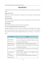
The User Manual of FIT Series General Frequency Inverter Compared with FIV Frequency Inverters, FIT series Frequency Inverter is mainly improved in the following aspects: Support various motors Support the vector control of three-phase AC asynchronous motor and three-phase AC permanent magnet synchronous motor. Rich control methods Apart from vector control of speed sensor, vector control of non-speed sensor and V/F, the machine also support separation control. Various encoders Support differential encoder, open collector encoder, rotary transformer, etc. The vector control algorithm of brand...

 Open the catalog to page 2
VTdrive FIT-Closed Loop VFD for Industrial-3

The User Manual of FIT Series General Frequency Inverter Unpacking inspection: Please confirm the following items carefully when unpacking: Confirm whether the type and the rated value as noted on the nameplate are consistent with the goods you order. The container contains your ordered product, product certificate, user manual and guarantee. Check whether the product is damaged in transportation. In case of any leakage or damage, please contact us or your supplier immediately. First use: The user who uses this product for the first time should understand this manual carefully. If you have any doubt...

 Open the catalog to page 3
VTdrive FIT-Closed Loop VFD for Industrial-4

The User Manual of FIT Series General Frequency Inverter 4.3 Organization mode of function code of Frequency Inverter42

 Open the catalog to page 4
VTdrive FIT-Closed Loop VFD for Industrial-5

The User Manual of FIT Series General Frequency Inverter

 Open the catalog to page 5
VTdrive FIT-Closed Loop VFD for Industrial-6

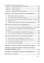
The User Manual of FIT Series General Frequency Inverter INSTALLATION SELECTION GUIDE FOR EMC EXTERNAL ACCESSORY 241 ELECTRICAL SPECIFICATION OF FIT SERIES FREQUENCY INVERTER.246

 Open the catalog to page 6
VTdrive FIT-Closed Loop VFD for Industrial-7

The User Manual of FIT Series General Frequency Inverter

 Open the catalog to page 7
VTdrive FIT-Closed Loop VFD for Industrial-8

The User Manual of FIT Series General Frequency Inverter

 Open the catalog to page 8
VTdrive FIT-Closed Loop VFD for Industrial-9

The User Manual of FIT Series General Frequency Inverter

 Open the catalog to page 9
VTdrive FIT-Closed Loop VFD for Industrial-10

The User Manual of FIT Series General Frequency Inverter The safety is defined as below: In this manual, the safety precautions are classified into two kinds: •Danger: The danger resulting from illegal operation may result in serious injury and even death; Attentions: The danger resulting from illegal operation may result in moderate injury or minor injury as well as equipment damage; Please understand this chapter well and make sure to comply with safety precautions as required hereof in the installation, debugging and maintenance of this system. Or else, any injury or loss resulting from illegal operation...

 Open the catalog to page 10
VTdrive FIT-Closed Loop VFD for Industrial-11

The User Manual of FIT Series General Frequency Inverter

 Open the catalog to page 11
VTdrive FIT-Closed Loop VFD for Industrial-12

The User Manual of FIT Series General Frequency Inverter

 Open the catalog to page 12
VTdrive FIT-Closed Loop VFD for Industrial-13

The User Manual of FIT Series General Frequency Inverter 1) The requirements for leakage protector RCD The equipment may bring the large leakage current which flows through the protective grounding conductor. Please install Type B leakage protector (RCD) in the primary side of the power supply. In selection of leakage protector (RCD), transient and steady earth leakage current that may occur shall be taken into account when the equipment is started and operated. Please select the exclusive RCD which can restrain the higher harmonic or the general RCD with large residual current. 2) Insulation...

 Open the catalog to page 13
VTdrive FIT-Closed Loop VFD for Industrial-14

The User Manual of FIT Series General Frequency Inverter 4) Operation above power frequency This Frequency Inverter will provide the output power which ranges from 0Hz to 3200Hz. If the user requires operation above 50Hz, please consider the bearing capacity of mechanical device. 5) Vibration of mechanical device The Frequency Inverter may meet the mechanical resonance point of load device at the point of some output frequency, which may be avoided by setting the hopping frequency parameter in Frequency Inverter. 6) Heat emission and noise of the motor The output voltage of frequency convertor...

 Open the catalog to page 14
VTdrive FIT-Closed Loop VFD for Industrial-15

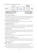
The User Manual of FIT Series General Frequency Inverter 9) Service beyond the rated voltage The Frequency Inverter shall not be beyond the allowable working voltage, the components of the Frequency Inverter may be damaged. If necessary, the related boost device or dropping device shall be used for the voltage transformation of power supply before input into the Frequency Inverter. 10) Change three-phase input into two-phase input It is not allowed to change three-phase Frequency Inverter into two-phase service, or else, the failure or any damage to the Frequency Inverter may occur. 11) Lightning...

 Open the catalog to page 15

All VTDRIVssE Technology Limited catalogs and technical brochures

*Prices are pre-tax. They exclude delivery charges and customs duties and do not include additional charges for installation or activation options. Prices are indicative only and may vary by country, with changes to the cost of raw materials and exchange rates.