
- Catalogs
- VTDRIVssE Technology Limited
- VTdrive FIE Series Frequency Inverter for motors

VTdrive FIE Series Frequency Inverter for motors

VTdrive FIE Series Frequency Inverter for motors
- Safety Information: Highlights the critical importance of following safety notices to prevent severe injury or death, categorizing notices into 'DANGER' and 'WARNING' based on severity.
- General Precautions: Provides guidelines for motor insulation tests, thermal protection, and handling AC drives under various conditions like high altitude and lightning protection.
- Designation Rules and Nameplate: Explains naming conventions and specifications on the FIE series nameplate.
- FIE Variable-frequency Drive Series: Includes a table with technical data for different models, detailing power capacity, input/output current, and compatible motor specifications.
- Mechanical Installation: Details proper installation procedures to ensure safety and functionality.
- Electrical Installation: Outlines correct wiring practices and emphasizes the importance of using qualified personnel for installation.
- Operation Panel: Describes the operation panel and functions of various keys.
- Provides a comprehensive list of function codes used in the FIE series.
- Offers detailed explanations of function codes grouped by parameters such as basic parameters, motor parameters, control parameters, etc.
- Routine Repair and Maintenance: Offers guidelines for regular maintenance to ensure longevity and performance.
- Faults and Solutions: Lists common faults and their solutions to aid in troubleshooting.
- RS-485 Communication Expansion Card Instruction: Provides instructions for using the RS-485 communication expansion card.
- FIE Modbus Communication: Details the Modbus communication protocol for the FIE series.
- Open Collector Output: Output voltage range is 0–24 V and output current range is 0–50 mA.
- High-Speed Pulse Output: Limited by P5-00, with a maximum frequency of 100 kHz.
- Relay Output: T/A-T/B NC terminal contact driving capacity is 250 VAC, 3 A, COS ø = 0.4, and 30 VDC, 1 A.
- Auxiliary Interface: Includes various interfaces for optional cards and external operation panels.
- AC Drive Control Circuit: All FIE series AC drives have the same wiring mode.
- Electric Wiring of the FIE: Detailed in Figure 3-8.
- Operation Panel: Allows modification of parameters, monitoring of working status, and control of the FIE.
- Digital Display: A 5-digit LED display shows set frequency, output frequency, monitoring data, and fault codes.
- Viewing and Modifying Function Codes: The operation panel uses a three-level menu system for function code management.
- Function Code Table: Includes standard function parameters, motor parameters, vector control parameters, V/F control parameters, and input terminal parameters.
This document provides detailed parameter settings for a technical system, likely related to a motor drive or similar equipment. It includes specifications for input/output settings, control modes, and fault protection mechanisms.
- VS Curve Settings: Parameters P4-26 to P4-34 define the input settings for VS curves.
- PULSE Settings: Parameters P4-28 to P4-32 cover pulse input settings.
- Delay Times: Parameters P4-35 to P4-37 specify delay times for various functions.
- Mode Selections: Parameters P4-38 to P4-40 detail mode selections for input signals and valid modes.
- Y2 Terminal Output Mode: Parameter P5-00 defines the output mode for the Y2 terminal.
- Relay Functions: Parameters P5-02 to P5-05 describe the functions of various relay outputs.
- Start Modes: Parameters P6-00 to P6-07 cover start modes.
- Stop Modes: Parameters P6-10 to P6-15 define stop modes and DC braking settings.
- LED Display Settings: Parameters P7-03 to P7-05 specify which parameters are displayed on the LED during operation and stop modes.
- Temperature and Version Information: Parameters P7-07 to P7-11 provide information on the inverter module temperature and software version.
- JOG Functions: Parameters P8-00 to P8-02 define JOG running frequency and acceleration/deceleration times.
- Frequency Detection: Parameters P8-19 to P8-21 cover frequency detection values and ranges.
- Overload Protection: Parameters P9-00 to P9-02 detail motor overload protection settings.
- Fault Auto Reset: Parameters P9-09 to P9-11 describe the auto-reset functionality for faults.
- The document provides comprehensive settings for configuring and managing a technical system, focusing on input/output parameters, control modes, and fault protection.
- Understanding each parameter's range and default settings is crucial for optimal system performance and troubleshooting.
The document outlines the selection and switchover of motor parameter groups using P0-24 or a DI terminal, with DI terminal selection taking precedence in case of conflict.
P0-25 defines the base frequency for acceleration/deceleration time.
P0-27 allows binding of command sources to frequency sources, facilitating synchronous switchover.
P0-28 specifies the serial communication protocol, supporting MODBUS, PROFIBUS-DP bridge, and CANopen bridge.
Group P1 details motor parameters such as type, power, voltage, current, frequency, and speed.
Parameters P1-27 to P1-36 cover encoder settings.
P1-37 outlines auto-tuning options for asynchronous and synchronous motors.
Group P2 is relevant for vector control, detailing speed loop proportional gain, integral time, and switchover frequencies.
Proper setting of parameters based on motor specifications and conditions is emphasized for optimal performance.
- Over-excitation Gain (P2-08): Used during deceleration to prevent over-voltage faults.
- Torque Upper Limit (P2-09, P2-10): Defines the maximum output torque in speed control mode.
- Excitation and Torque Adjustment Gains (P2-13 to P2-16): These are PI parameters for vector control.
- Field Weakening (P2-18 to P2-22): Controls the maximum rotational speed of synchronous motors.
- V/F Curve Setting (P3-00): Determines the relationship between voltage and frequency.
- Torque Boost (P3-01, P3-02): Enhances low-frequency torque by boosting output voltage.
- Multi-point VF Curve (P3-03 to P3-08): Customizes the VF curve based on motor load characteristics.
- VF Slip Compensation (P3-09): Stabilizes motor speed by compensating for slip during load changes.
- VF Over-excitation Gain (P3-10): Prevents over-voltage during deceleration.
- VF Oscillation Suppression (P3-11): Minimizes oscillation in VF control.
- VF Separation (P3-13 to P3-16): Allows independent control of output voltage and frequency.
- Provides multiple digital and analog input options for controlling various functions.
- Proper parameter setting is crucial to prevent faults and ensure optimal performance.
- Automatic tuning is available for certain parameters, but manual adjustments may be necessary.
- Field weakening and VF separation offer advanced control options for specific motor applications.
The document provides detailed technical specifications and configuration options for the Y2 terminal, a programmable multiplexing terminal used in AC drives.
- Y2 Terminal Functions: Can be used for high-speed pulse output or as an open collector switch signal output.
- Parameter Settings: Includes P5-01 to P5-22 for configuring digital output terminals, relay functions, and delay times.
- Pulse and Analog Output: Y2P terminal frequency ranges from 0.01 kHz to 100 kHz.
- Function Selection: Parameters P5-01 to P5-05 are used to select functions for digital output terminals.
- Output Delay Time: Parameters P5-17 to P5-21 set delay times for output terminals.
- Logic Settings: P5-22 sets the logic of output terminals.
- Start/Stop Control: P6-00 to P6-07 define start modes and acceleration/deceleration modes.
- Maximum Y2P Output Frequency: P5-09 sets the maximum frequency for pulse output.
- AO1 and AO2 Adjustments: Parameters P5-10 to P5-13 allow for zero offset and gain adjustments.
- S-Curve Acceleration/Deceleration: P6-08 and P6-09 define time proportions for S-curve start and end segments.
The document provides comprehensive guidance on configuring and optimizing the Y2 terminal for various operational needs.
- Decelerate to Stop (P6-10): The AC drive reduces output frequency according to deceleration time until it reaches zero.
- Coast to Stop: The AC drive stops output immediately, allowing the motor to coast based on mechanical inertia.
- Initial Frequency (P6-11): DC braking starts when running frequency is below this value.
- Waiting Time (P6-12): Time delay before DC braking starts to prevent overcurrent faults.
- Braking Current (P6-13): Specifies output current during DC braking as a percentage of the base value.
- Braking Time (P6-14): Duration of DC braking; setting to 0 cancels braking.
- MF Key Function (P7-01): Configures multifunctional key for various operations.
- STOP/RESET Key (P7-02): Determines if the key is enabled in all operation modes or only on the panel.
- LED Display Parameters (P7-03 to P7-05): Sets parameters to be displayed during running or stop states.
- Load Speed Display (P7-06, P7-12): Adjusts relationship between output frequency and load speed.
- JOG Parameters (P8-00 to P8-02): Defines frequency and acceleration/deceleration times for jogging.
- Acceleration/Deceleration Times (P8-03 to P8-08): Provides multiple groups for different operational needs.
- Jump Frequency (P8-09 to P8-11): Helps avoid mechanical resonance by setting jump frequencies.
- Reverse Control (P8-13): Enables or disables reverse rotation.
- Running Mode (P8-14): Sets mode when frequency is below the lower limit.
- Droop Control (P8-15): Balances workload among multiple motors by adjusting output frequency.
- Accumulative Time and Power (P8-16 to P8-17): Sets thresholds for power-on and running times.
- Startup Protection (P8-18): Ensures safety by requiring run command validation after power-on or fault reset.
- Frequency Detection (P8-19 to P8-33): Configures detection values and hysteresis for frequency monitoring and control.
This document provides detailed technical specifications and operational procedures for an AC drive system, focusing on sensor compatibility, fault protection, process control, and PID functions.
The AC drive supports both PT100 and PT1000 sensors.
The document outlines actions during instantaneous power failures and load protection.
The PID function is crucial for process control, adjusting output frequency based on feedback.
The document describes PID parameter switchover conditions and initial value settings.
Parameters for swing frequency control and fixed length control are provided.
The document is a comprehensive guide for configuring and operating an AC drive system.
The document outlines the configuration and operation of a control system involving pulse counting and length measurement.
The multi-reference function allows for setting sources of frequency, V/F separated voltage, and process PID.
Group PD covers communication parameters, and Group PP addresses user security with password protection.
Group A0 focuses on torque control, offering options for speed or torque control modes.
Group C parameters are used to monitor the inverter's running state.
This section outlines the parameters for monitoring and controlling an AC drive.
Routine Maintenance: Regular checks are necessary to ensure the AC drive operates efficiently.
VTdrive Technology Limited offers an 18-month warranty for AC drives under normal use.
The document provides a comprehensive list of potential faults with corresponding error codes and solutions.
This section offers a quick reference for troubleshooting common issues encountered during AC drive operation.
Possible causes include no power supply, faulty switch power supply, damaged rectifier bridge, faulty control board or operation panel, and broken cables.
This may be due to poor cable contact, damaged control board components, short-circuited motor or cable, faulty HALL device, or low power input.
Caused by short-circuited motor or output cable, or damaged AC drive.
Caused by a damaged cooling fan or short-circuited external control terminal cable.
Caused by high carrier frequency, damaged cooling fan, or blocked air filter.
Caused by improper motor parameters, poor cable contact, or faulty drive board.
Caused by incorrect parameter settings, incorrect external signal, or loose jumper bar.
Caused by faulty encoder, incorrect encoder cable connection, or faulty PG card.
Caused by improper motor parameters, improper acceleration/deceleration time, or fluctuating load.
Caused by a soft startup contactor not picked up.
Caused by damaged control board components.
Details installation dimensions, control terminals, and jumper settings for RS-485 communication.
Describes the RS485 communication interface supporting Modbus RTU protocol.
This section outlines the command addresses and their corresponding control functions for digital outputs.
The document specifies command addresses for controlling analog outputs AO1 and AO2.
Similar to analog outputs, the PULSE output control uses a command address with values from 0 to 7FFF.
This section provides a comprehensive list of inverter fault codes and their descriptions.
The document details various communication parameters, including:
- Baud Rate (Pd-00): Sets the data transfer rate between the host computer and the inverter.
- Data Format (Pd-01): Specifies the data format for communication.
- Local Address (Pd-02): Defines the unique local address for point-to-point communication.
- Response Delay (Pd-03): Sets the interval time from receiving to sending data.
- Communication Overtime (Pd-04): Determines the maximum interval time between communications.
- Communication Protocol Selection (Pd-05): Allows selection between non-standard and standard Modbus protocols.
- Communication Read Current Resolution (Pd-06): Sets the unit for output current value.
Catalog excerpts

FIE Series Frequency Inverter FIE Series Frequency Inverter User Manual
Open the catalog to page 1
FIE Series Frequency Inverter
Open the catalog to page 2
FIE Series Frequency Inverter
Open the catalog to page 3
In this manual, the notices are graded based on the degree of danger: ' DANGER indicates that failure to comply with the notice will result in severe personal injury or even death. WARNING indicates that failure to comply with the notice will result in personal injury or property damage. Read this manual carefully so that you have a thorough understanding. Installation, commissioning or maintenance may be performed in conjunction with this chapter. VTdrive Technology Limited will assume no liability or responsibility for any injury or loss caused by improper operation.
Open the catalog to page 4
• Repair or maintenance of the AC drive may be performed only by qualified personnel. Failure to comply will result in personal injury or damage to the AC drive. • Do not repair or maintain the AC drive at power-on. Failure to comply will result in electric shock. • Repair or maintain the AC drive only ten minutes after the AC drive is powered off. This allows for the residual voltage in the capacitor to discharge to a safe value. During maintenance Failure to comply will result in personal injury. DANGER • Ensure that the AC drive is disconnected from all power supplies before starting repair...
Open the catalog to page 7
Motor heat and noise The output of the AC drive is pulse width modulation (PWM) wave with certain harmonic frequencies, and therefore, the motor temperature, noise, and vibration are slightly greater than those when the AC drive runs at power frequency (50 Hz). 6) When external voltage is out of rated voltage range The AC drive must not be used outside the allowable voltage range specified in this manual. Otherwise, the AC drive's components may be damaged. If required, use a corresponding voltage step-up or step-down device. 7) Contactor at the I/O terminal of the AC drive When a contactor is...
Open the catalog to page 8
generated when the plastic parts are burnt. Treat them as ordinary industrial waste 14) Adaptable Motor • The standard adaptable motor is adaptable four-pole squirrel-cage asynchronous induction motor or PMSM. For other types of motor, select a proper AC drive according to the rated motor current. • The cooling fan and rotor shaft of non-variable-frequency motor are coaxial, which results in reduced cooling effect when the rotational speed declines. If variable speed is required, add a more powerful fan or replace it with variable-frequency motor in applications where the motor overheats easily....
Open the catalog to page 9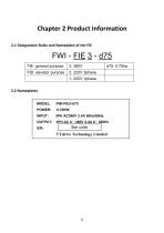
2.1 Designation Rules and Nameplate of the FIE MODEL: POWER: INPUT: OUTPUT: S/N:
Open the catalog to page 10
Figure 2-1 Inverter model and technical data
Open the catalog to page 11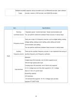
Multiple encoderIt supports various encoders such as differential encoder, open-collector Types encoder, resolver, UVWencoder, and SIN/COS encoder.
Open the catalog to page 14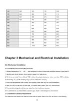
1. Ambient temperature -10"C~40"C, Well ventilated or indoor Spaces with ventilation devices, more than 40 "C derating use. Avoid vibration, direct sunlight, away from heat source. 2. AC drives can install where altitude 1000 m below the output rated power, when more than 1000 m altitude need derating use, specific derating range, please contact the company. 3. Avoid high temperature high humidity, the humidity is less than 90% RH (Non-condensate). 4. Apart from the oil, salt and corrosive gas. To prevent water, steam, dust, lint, metal powder. 5. Prevent electromagnetic interference, away from...
Open the catalog to page 17
Power level The FIE series AC drive dissipates heat from the bottom to the top. When multiple AC drives are required to work together, install them side by side. For application installing multiple AC drives, if one row of AC drives need to be installed above another row, install an insulation guide plate to prevent AC drives in the lower row from heating those in the upper row and causing faults. 3.1.3 Mounting dimension 1) Online example
Open the catalog to page 18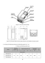
output hole Bottom case install hole Figure 3-2 FIE series Plastic structure shape dimension and installation dimension sketch 2) FIE series VFD Mounting dimension and Mounting position size (mm) 3-1 Exterior and Mounting position size
Open the catalog to page 19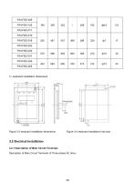
Figure 3-3 keyboard installation dimensions Figure 3-4 keyboard installation hole size 3.2 Electrical Installation 3.2.1 Description of Main Circuit Terminals Description of Main Circuit Terminals of Three-phase AC drive
Open the catalog to page 21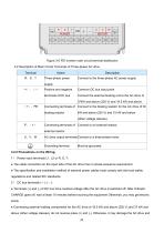
3-2 Description of Main Circuit Terminals of Three-phase AC drive 3.2.2 Precautions on the Wiring: 1) Power input terminals L1, L2 or R, S, T: • The cable connection on the input side of the AC drive has no phase sequence requirement. • The specification and installation method of external power cables must comply with the local safety regulations and related IEC standards. 2) DC bus terminals (+), (—): • Terminals (+) and (-) of DC bus have residual voltage after the AC drive is switched off. After indicator CHARGE goes off, wait at least 10 minutes before touching the equipment Otherwise, you...
Open the catalog to page 22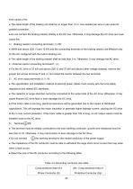
even cause a fire. ● The cable length of the braking unit shall be no longer than 10 m. Use twisted pair wire or pair wires for parallel connection. ● Do not connect the braking resistor directly to the DC bus. Otherwise, it may damage the AC drive and even cause fire. 3) Braking resistor connecting terminals (+), PB: ● 30kW and above (220 V) and 15 kW and the connecting terminals of the braking resistor are effective only for the AC configured with the built-in braking unit. ● The cable length of the braking resistor shall be less than 5 m. Otherwise, it may damage the AC drive. 4)External reactor...
Open the catalog to page 23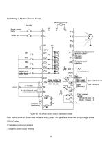
3.2.4 Wiring of AC Drive Control Circuit Braking resistor Extension card ■jqv setting frequency 'collector 1 (High-speed 'pulse output) Paul contact I output Figure 3-7 AC drives control circuit connection mode Note: All FIE series AC drives have the same wiring mode. The figure here shows the wiring of single-phase 220 VAC drive. ◎ indicates main circuit terminal o indicates control circuit terminal.
Open the catalog to page 26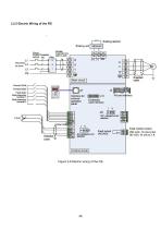
Braking unit MDBUN breaker Contactor magnetic core MultH ir'e'erce Fault contact output Fautt output
Open the catalog to page 27All VTDRIVssE Technology Limited catalogs and technical brochures
 VS5 Solar pump inverter
3 Pages
 VTdrive What is a Choke Coil
2 Pages















Archived catalogs

- Electronic filter
- Passive electronic filter
- AC electronic filter
- Wire-wound resistor
- Solar DC/AC inverter
- Three-phase electronic filter
- 3-phase frequency converter
- Choke coil
- Three-phase DC/AC inverter
- DC/AC inverter for industrial applications
- Band-pass electronic filter
- EMI filter
- Housed resistor
- Compact frequency inverter
- IP20 frequency inverter
- Digital output frequency inverter
- Motor frequency converter