- Catalogs
- VSE Volumentechnik GmbH
- RS helical screw flow meter
RS helical screw flow meter
1 /20Pages

RS helical screw flow meter
1 /20Pages
Catalog excerpts

fluid technology solutions
Open the catalog to page 1
RS flow meters measure the flow rate based on the screw pump principle. A pair of rotors fitted precisely into the housing constitutes the measuring element. An integrated gear and non-contact signal pick-up system detects the rotations of the measuring element and converts them to digital pulses. Together with the housing walls, the rotor edges form closed measuring chambers in which the fluid is transported from the inlet to the outlet side. The fluid volume put through within one main rotor rotation is the rotation volume, which is divided by the sensing gear and digitised, processed and output...
Open the catalog to page 2
FREQUENCY RANGE 0 ... 100 kHz, adjustable MEASUREMENT ACCURACY ± 0.5 % (1 %)** of measured value with viscosity of > 21 cSt. REPEATABILITY ACCURACY ± 0.05 % with same operating conditions **RS 800 RS 2500 MATERIALS GRAY CAST IRON MODEL EN-GJS-400-15 (EN 1563)/16 Mn Cr 5 or 1.4112 (depending on size) STAINLESS STEEL MODEL Stainless steel 1.4305/1.4112, additional available upon request BEARING Fluid-dependent as anti-friction bearing or SSIC/wolf-ram carbide friction bearing SEAL FPM (standard) PTFE, NBR, EPDM upon request FLUID TEMPERATURE -40°C ... +210°C (HT design) -30°C ... +120°C (standard)...
Open the catalog to page 3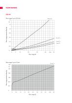
FLOW RANGES SIZE 40 Flow range 0 up to 50 l/min Flow range pressure drop ∆p Flow range 0 up to 5 l/min Flow range pressure drop ∆p
Open the catalog to page 4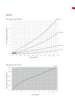
SIZE 100 Flow range 0 up to 120 l/min Flow range pressure drop ∆p Flow range 0 up to 10 l/min Flow range pressure drop ∆p
Open the catalog to page 5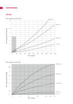
FLOW RANGES SIZE 400 Flow range 0 up to 500 l/min Flow range pressure drop ∆p Flow range 0 up to 50 l/min 4 Flow range pressure drop ∆p
Open the catalog to page 6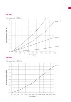
SIZE 800 Flow range 0 up to 1,000 l/min Flow range pressure drop ∆p Flow range Q SIZE 2500 Flow range 0 up to 3,000 l/min 1.8 2 Flow range pressure drop ∆p
Open the catalog to page 7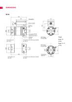
Preamplifier Sensor module Earthing Ø6 Connection PT100 Temperature sensor 27 Test port G1/4 Connection unit with sensor module AR. 40- D.. M6-9 deep on both sides M6-9 deep on both sides Connection unit with sensor module AR. 40-T..
Open the catalog to page 8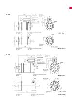
Connection unit AR. 100-T. Connection unit AR. 100-T. Connection unit with sensor module AR. 100-E.. Connection unit with sensor module AR. 100-E.. 36 36 Connection unit AR. 100-E.. Connection unit AR. 100-E.. Test port Preamplifier p G 1/4 Test port Preamplifier p Sensor module G 1/4 Sensor module Test port p G 1/4 Test port p Connection PT100 G 1/4 Temperature sensor Connection PT100 26 Temperature sensor 26 116 116 Connection SAE 3/4 Connection SAE 3/4 Connection unit with sensor module AR. 100-T.. Connection unit with sensor module AR. 100-T.. 4 x M10–18 deep 4 x M10–18 deep Weight 12.7 kg...
Open the catalog to page 9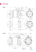
Sensor module Connection PT100 Temperature sensor Connection unit with sensor module AR. 800-H.. 57 Connection unit with sensor module AR. 800-X.. Sensor module Connection PT100 Temperature sensor SAE 4 + DN 100 PN 40 Flange connection dimensions DIN EN 1092 M8–15 deep TK 230 on both sides
Open the catalog to page 10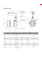
IRIS High temperature
Open the catalog to page 11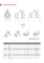
BRACKET CONNECTIONS RS Size
Open the catalog to page 12
SENSOR ELECTRONICS DESCRIPTION A special sensor system detects any movement of the pair of rotors or of the liquid column. For this purpose, a precision gear connected to a shaft of the rotor pair is scanned by a special magnetoresistive sensor. The scanning sensor includes two GMR-bridges (sin/cos) and is housed in a removable stainless steel cartridge case together with a signal conditioning and amplifier unit. The downstream electronics unit features a high-resolution sin/cos-interpolator, which is adjustable with ten different resolution factors. Furthermore, a programmable signal filter...
Open the catalog to page 13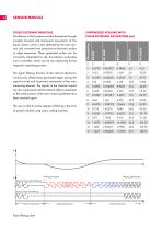
SENSOR MODULE PULSE FILTERING PRINCIPLE Oscillations in fluid systems manifest themselves through constant forward and backward movements of the liquid column, which is also detected by the rotor sensors and converted into proportional electronic pulses or edge sequences. These generated pulses can be incorrectly interpreted by the downstream evaluating unit or controller, which can be very distracting for the respective operating process. The signal filtering function of the internal electronics continuously offsets these generated edges during the rapid forward and backward movements of the...
Open the catalog to page 14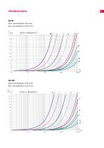
TECHNICAL DATA RS 40 Max. permissible flow 48 l/min Min. permissible flow 0.04 l/min
Open the catalog to page 15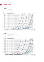
TECHNICAL DATA RS 400 Max. permissible flow 525 l/min Min. permissible flow 0.5 l/min RS 800 Max. permissible flow 1,050 l/min Min. permissible flow 5 l/min
Open the catalog to page 16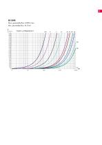
FLOW vs FREQUENCY Durchfluss vs. FREQUENZ
Open the catalog to page 17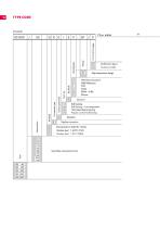
TYPE CODE
Open the catalog to page 18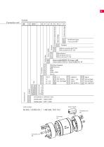
Connection unit AR 800 Modification figure Factory provided Without connection for PT 100 With connection for PT 100 Without test port With one test port G 1/4 With two test ports G 1/4 Gensoi inudule GOM 01 No longer valid Sensor module GSM 02 + Sensor module RS / HT FPM (Viton) Standard NBR (Perbunan) PTFE EPDM EPDM -41B8 Silicone Order example
Open the catalog to page 19
VSE Volumentechnik GmbH Hönnestraße 49 58809 Neuenrade / Germany 0 TÜV NORD CERT GmbH Phone +49 (0) 23 94 / 6 16-30 [email protected] www.vse-flow.com
Open the catalog to page 20All VSE Volumentechnik GmbH catalogs and technical brochures
 VSE Flow measurement technology
36 Pages
 VS gear flow meter
27 Pages
 VHM gear flow meter
16 Pages
 VSE EF ECOFLOW gear flow meter
12 Pages
 VTR turbine flow meter
8 Pages
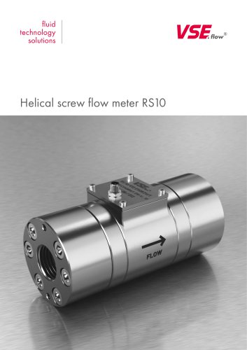 Helical screw flow meter RS10
4 Pages
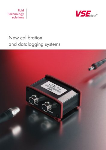 Cal.flow & Log.flow
8 Pages
 Signal converter FU210-28
2 Pages
- Display module
- Volume flow monitor
- Liquid flow monitor
- Data logger
- Calibration system
- Waterproof flow meter
- Stainless steel flow monitor
- Industrial flow monitor
- Touch screen display panel
- Precision flow meter
- USB datalogger
- In-line flow meter
- Water flow monitor
- Compact flow monitor
- DC flow monitor
- RS485 flow monitor
- Flow meter with display
- Digital flow monitor
- IP65 flow monitor