- Catalogs
- VS Sensorik GmbH
- Magnetic gear wheel encoder RGM2G-D with interpolated TTL output signals
Magnetic gear wheel encoder RGM2G-D with interpolated TTL output signals
1 /4Pages

Magnetic gear wheel encoder RGM2G-D with interpolated TTL output signals
1 /4Pages
Catalog excerpts
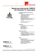
Magnetic gear wheel encoder RGM2G-D with interpolated TTL output signals Contactless incremental encoder for measuring rotary motion High-resolution measurement of rotational speed and rotational angle up to 60,000 1/min Rotational direction recognition Robust, not sensitive to dirt Temperature stability up to 110°C High EMC and ESD stability Bespoke specifications due to a flexible design principle Interpolations factor configurable ex works I2C interface for the fine-tuning of signal parameters if required Use in drive spindles of machine tools Installation in drive motors Output signals 90° phase shifted TTL square-wave signals/RS422 Reference pulse Remote Sense RS_UB Supply voltage UB = 5V Reverse voltage protection Short-circuit proof Principle of measurement Magnetic, contactless gauging of the steel gear wheels with module M = 0.3 or 0.5 Use of magneto-resistive (GMR) sensor elements High degree of measurement accuracy when using e.g. type ZR3-256/Di or ZR5-256/Di measuring gear wheels Internal interpolation electronic ... for gear wheel module M = 0.3 Robust metal sensor housing GMR-Sensor elements Frontal coverage of the sensor elements using metal foil to act as extra protection against ESD impulses Electronics for signal conditioning Complete sealing of sensor interior Screened connection cable with AWG28 Optional connector plug ... for gear wheel module M = 0.5 Datei: VS-Sensorik_DB_E_RGM2D Version: 2 Blatt: 1 Datum: 01.11.2011
Open the catalog to page 1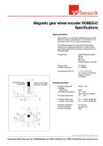
Magnetic gear wheel encoder RGM2G-D Specifications Signal parameters Before delivery, each encoder is balanced at the nominal distance encoder - gear wheel do = 0.1mm (for M = 0.3) and 0.3mm (for M = 0.5) on optimal signal values. The signal parameters may deviate from the optimal values due to subsequent tolerances of attached parts, gear wheel quality and the influence of temperature and rotational speed. Signal type digital, differential signals Spur A, Spur B Ref. pulse Inverted signals A, B & Ref. Output level Output Frequency f Position of the signal channels A, B & Ref. Optimal distance...
Open the catalog to page 2
Magnetic gear wheel encoder RGM2G-D Assembly & Electrical connection Gear Wheel Reference mark The arrow indicates the direction of movement during counter-clockwise rotation of the gear wheel with a view The encoder is assembled using the following procedure: 1. Gauge blocks of the corresponding gauges do are located on the front side of the encoder. 2. Fix the encoder using 2 M4 screws. The screws are still not firmly tightened. The encoder should be loose. 3. Push the encoder slightly against the gear wheel. Completely tighten the screws alternately. 4. After screwing the encoder tightly,...
Open the catalog to page 3
Magnetic gear wheel encoder RGM2G-D Order identifiers & Accessories Connector plug (optional) Cable length in cm (e.g. "050" for 50cm) Optional: Number of teeth of the gear wheel N, if N is considerably different from 256 (e.g. "064" if N = 64) Type of the reference mark (e.g. "Z", "F" or "L"): Z - Type ? - other types on request 3 - for gear wheel module M = 0.3 5 - for gear wheel module M = 0.5 Position of Signal tracks - "M" or "V": M Accessories Measuring gear wheels: ZR3-256/Di or ZR5-256/Di Other types of gear wheels on request. Datei: VS-Sensorik_DB_E_RGM2D Version: 2 Blatt: 4 Datum: 01.11.2011...
Open the catalog to page 4All VS Sensorik GmbH catalogs and technical brochures


- Angular encoder
- Proximity switch
- Calibration system
- Incremental rotary encoder
- Cylindrical proximity sensor
- Hollow-shaft rotary encoder
- IP67 proximity sensor
- Magnetic rotary encoder
- Ultra-rugged rotary encoder
- Stainless steel proximity sensor
- Magnetic proximity sensor
- Mechanical rotary encoder
- Analog rotary encoder
- Magnetic speed sensor
- Rotational speed sensor
- Non-contact proximity sensor
- Gear rotary encoder
- High-pressure proximity sensor
- Explosion-proof speed sensor