- Catalogs
- VS Sensorik GmbH
- Magnetic gear wheel encoder RGK2H-A-M1Z with anlog output signals
Magnetic gear wheel encoder RGK2H-A-M1Z with anlog output signals
1 /4Pages

Magnetic gear wheel encoder RGK2H-A-M1Z with anlog output signals
1 /4Pages
Catalog excerpts

Magnetic gearwheel encoder RGK2H-A-M1Z with anlog output signals Contactless incremental encoder for measuring rotary motion ■ High-resolution measurement of rotational speed and rotational angle ■ Magnetic, contactless gauging of the steel gearwheels ■ Rotational direction recognition ■ Robust, not sensitive to dirt ■ Bespoke specifications due to a flexible design principle ■ Potentiometer or I2C interface for the fine-tuning of signal parameters if required Use in drive spindles of machine tools Installation in drive motors Output signals ■ Remote Sense RSJJB ■ Reverse voltage protection ■ Robust metal sensor housing ■ Frontal coverage of the sensor elements using metal foil to act as extra protection against ESD impulses ■ Electronics for signal conditioning ■ Complete sealing of sensor interior ■ Screened connection cable with AWG26 ■ Optional connector plug ... for gear wheel module M = 1.0
Open the catalog to page 1
Magnetic gear wheel encoder RGK2H-A-M1Z Specifications Signal parameters Before delivery, each encoder is balanced at the nominal distance encoder - gear wheel do = 0.5mm on optimal signal values (amplitude - see table, offset 0 mV, phase 90°, unambiguousness of the reference pulse). The signal parameters may deviate from the optimal values due to subsequent tolerances of attached parts, gear wheel quality and the influence of temperature and rotational speed. Signal type Analog, differential signals SIN (spur A), COS (spur B) Ref. pulse Inverted signals A, B & Ref. Signal amplitude A & B Amplitude...
Open the catalog to page 2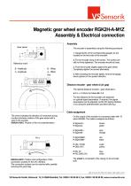
Magnetic gear wheel encoder RGK2H-A-M1Z Assembly & Electrical connection Assembly Gear wheel 1. Gauge blocks of the corresponding gauges do are located on the front side of the encoder. The encoder is assembled using the following procedure: 2. Fix the encoder using 4 M3 screws. The screws are still not firmly tightened. The encoder should be loose. Reference mark B - Amplitude A - Amplitude 3. Push the encoder slightly against the gear wheel. Completely tighten the screws alternately. 4. After screwing the encoder tightly, remove the gauge block (spacer) in the upward direction. Distance encoder...
Open the catalog to page 3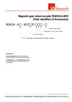
Magnetic gear wheel encoder RGK2H-A-M1Z Order identifiers & Accessories Connector plug (optional) Cable length in cm (e.g. "050" for 50cm) A or I : Parameter of output signals see table on page 2 Accessories External interpolation box for the digitalisation and interpolation of the analogue encoder signals PB-RGMA-USB box with SPB-RGMA-USB software for the fine alignment of encoder signals via the I2C-interface Datei: VS-Sensorik_DB_E_RGK2H-A-M1Z Version: 1 Blatt: 4 Datum: 14.02.2011
Open the catalog to page 4All VS Sensorik GmbH catalogs and technical brochures


- Angular encoder
- Proximity switch
- Calibration system
- Incremental rotary encoder
- Cylindrical proximity sensor
- IP67 proximity sensor
- Hollow-shaft rotary encoder
- Magnetic rotary encoder
- Ultra-rugged rotary encoder
- Stainless steel proximity sensor
- Magnetic proximity sensor
- Mechanical rotary encoder
- Analog rotary encoder
- Magnetic speed sensor
- Rotational speed sensor
- Non-contact proximity sensor
- Gear rotary encoder
- High-pressure proximity sensor
- Explosion-proof speed sensor