

Bevel helical gearboxes

Bevel helical gearboxes
The bevel helical gearboxes are designed for demanding industrial applications, offering versatility, easy installation, adaptability, and cost-effectiveness. They are suitable for general machinery, special purpose machines, lifting gear, crane installations, rolling mills, cable installations, conveyor drives, and stranding machinery.
The gearboxes feature a two-stage design with a bevel gearset for input and a helical gearset for output. Constructed from high-quality grey cast iron, they ensure durability and high efficiency. The modular design allows for various modifications.
The first stage uses Klingelnberg palloid-spiral gearing, allowing high torque transmission. The gears are made from alloy steel, hardened, and lapped for quiet operation, reduced backlash, and good efficiency.
Gearboxes are available with different ratios and designs, including solid shaft, hollow shaft, and flange options. Types include KS, KSH, KSHF, MKS, MKSH, and MKSHF.
The housing is made from cast iron or aluminum, with options for stainless steel and galvanic coating. Shafts are made from C45 or 42 Cr Mo 4+QT steel, with options for stainless steel or chromium coating. Bevel and helical gears are optimized for low noise and high torque, made from 16 Mn Cr 5 or 17 Cr Ni Mo 6 steel.
The input and output shaft directions are interdependent, with sides identified by letters A to F. Bevel gears are positioned on sides C and B, with side C as the input. Rotation directions are defined as clockwise or counterclockwise.
Lubrication options include mineral and synthetic oils, with special oils for food processing and extreme temperatures. The gearboxes are designed for easy maintenance and long bearing life.
The document provides detailed specifications for gear ratios ranging from 6.0 to 48.0, including specific configurations with hypoid gearsets for higher ratios. It lists various types such as KS, KSH, KSHF, MKS, MKSH, MKSF, and MKSHF, and notes that all mentioned ratios are mathematically exact, with other ratios available upon request.
Backlash is measured at 2% of the nominal output torque. Two quality standards are offered: Standard 1 is free, while Standard 2, available for sizes 1 to 16, incurs an additional cost. Certificates for backlash and runout error can be provided.
The efficiency of the gearbox is dependent on its nominal power. The document provides a table showing efficiency values for different gear sizes and ratios.
When calculating the maximum required input power, factors such as shock factor (c1) and ambient temperature (c2) must be considered. The document provides formulas and tables to calculate input power and select the appropriate gearbox size based on these conditions.
Gearboxes are supplied with oil filling, and for sizes 8 to 128, breather plugs must be fitted. The first oil change is required after 500 operating hours, with subsequent changes every 3000 hours. Different oil grades are recommended based on the gear ratio, with specific oils listed for ratios 6 to 28.8 and 33.6 to 48.
The nominal output torque can be temporarily overloaded by a factor of 1.8, with emergency stop output torque permissible for up to 1000 stops.
The document provides detailed specifications for motor and gearbox components, including dimensions and mounting instructions. Key parameters include motor shaft diameter, centring diameter, pitch circle diameter, and motor shaft length. Various sizes and configurations are outlined, such as square and round flanges, with specific measurements for each.
Instructions for motor mounting are provided for different gearbox sizes (8-32, 64-128, and 1-4). The document emphasizes the importance of using a keyway for certain sizes and provides step-by-step assembly instructions, including torque specifications for tightening screws.
The document recommends using motors with reduced shaft tolerance and concentricity according to DIN 42955 R standards for optimal performance. It also highlights the necessity of ensuring that motor shafts and clamping sleeves are free from dirt and grease before assembly.
The tables provide possible motor shaft and flange dimensions, along with the maximum torque transmission capabilities of shrink disk couplings. Specific screw sizes and quality standards are also listed.
Attention is drawn to the requirement of using motor shafts with keyways for gearbox sizes 8-32 to ensure torque transfer during emergency stops. The document also specifies that certain designs are not available for gearbox size 128.
The document provides detailed specifications for various types of gearboxes, specifically focusing on the inertia types KS, KSH, MKS, and MKSH. It includes data on size, translation ratios, and mass moments of inertia, with values given in kgcm².
Instructions are provided for the operation of gearboxes, emphasizing the importance of ensuring the oil pump is running before starting the gearbox. The document also outlines the electrical connection data for the oil pump, including power, voltage, speed, and protection type.
The document specifies permissible radial and axial loads for input and output shafts at various speeds and gearbox sizes. It also highlights the thermal power limits of bevel helical gearboxes under specific conditions, such as maximum input speed, ambient temperature, and operation mode.
The tables provide extensive data on permissible loads, inertia values, and thermal ratings across different gearbox sizes and speeds. Key data includes:
- Permissible radial and axial loads for input and output shafts at various speeds and gearbox sizes.
- Mass moments of inertia for different gearbox types and sizes.
- Thermal power limits for bevel helical gearboxes under specified conditions.
The document includes contact information for Lenze distribution partners across various regions, including Germany, Australia, Austria, Belgium, Brazil, China, Czech Republic, Denmark, Finland, France, Hungary, India, Iran, Israel, Italy, Korea, Lithuania, Latvia, Estonia, and Mexico.
Catalog excerpts

Kegelstirnradgetriebe · Bevel Helical Gearboxes SERVO gears Mechanical gears Industrial gears
Open the catalog to page 1
Inhaltsverzeichnis Contents Ubersetzungsplan, Verdrehspiel Wartung - Schmierung - Gewichte 14 Abmessungen Typ KSHF / MKSHF 36 Alternativen Typ KSHF / MKSHF 37 Ratio plan, Backlash Selecting the right size 12 Maintenance - Lubricant - Weight 14 Dimensions type MKS / MKSH / Dimensions type MKS / MKSH / Possible motor flange dimensions 29 Dimensions type MKS / MKSH / Dimensions type MKS / MKSH / Possible motor flange dimensions 31 Dimensions type MKS / MKSH / Dimensions type MKS / MKSH / Possible motor flange dimensions 33 Coupling assembly design for gearbox type KSH / KSHF / Dimensions type KSHF/MKSHF...
Open the catalog to page 2
Entwickelt und gefertigt für höchste Ansprüche und wirtschaftlich rentablen Einsatz. Developed and manufactured for economic use in demanding industrial applications. universell einsetzbar einbaufreundlich und anpassungsfähig maschinengerechte Konstruktion kostensparend Nutzen Sie die in Jahrzehnten bewährten Vorteile des Getriebespezialisten mit dem hohen Qualitätsstandard und dem anerkannten know-how. - kompaktes Baukastensystem geringes Leistungsgewicht hoher Wirkungsgrad geräuscharm wartungsfreundlich universal usable easy to fit and adaptable easy to design and retrofit save cost Make use...
Open the catalog to page 3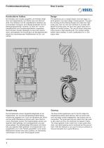
Konstruktiver Aufbau Die Getriebe sind 2-stufig ausgeführt, der Eintrieb erfolgt über eine Kegelradstufe, der Abtrieb über eine Stirnradstufe. Das Gehäuse und die Lagerflansche bestehen aus hochwertigem Grauguss, sind allseitig bearbeitet und mit Befestigungsgewinden versehen. An allen Ein- und Abtriebsflanschen sind Zentriermöglichkeiten vorgesehen. Durch Einsatz robuster Wälzlager ist eine hohe Lebensdauer sichergestellt. Die Konstruktion als Baukastensystem erlaubt die verschiedensten Modifikationen an Ein- und Abtrieb. The gearboxes are a 2-stage design, the input stage is a bevel gearset,...
Open the catalog to page 4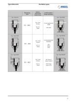
Available types Übersetzung Ratio Abtriebsdrehmoment Output torque Ausführungsform Design description Typ / Type MKS mit durchgehender Welle with shaft mit durchgehender Hohlwelle with hollow shaft Mit Flansch Seite A oder B With flange side A or B
Open the catalog to page 5
Technische Daten Ausführung Werkstoff Ausführung Toleranz Werkstoff Sonderausführung Ausführung Toleranz Werkstoff Sonderausführung Werkstoff Sonderausführung Rechteckform Befestigungsgewinde im Gehäuse-KS= 1,5 x ø Grauguss EN-GJL-250 (EN-JL-1040) bzw. Sphäroguss EN-GJS-400-15 (EN-JS-1040) bzw. EN AC-ALS: 10 Mg a T6 (EN-AB-43000) Gehäuse und Flansche aus Aluminium Stahlguss oder Schweisskonstruktion Nichtrostende Ausführung Galvanische Oberflächenbehandlung Wellenzentrierung nach DIN 332, Blatt 2 Passfelder nach DIN 6885, Blatt 1 j6 bzw. k6 C 45 (1.0503) bzw. 42 Cr Mo 4+QT (1.7225) Nichtrostende...
Open the catalog to page 6
Technical data Design Material Special design Design Tolerance Material Special design Hollow shaft Design Tolerance Material Special design rectangular formed Attachment thread in the housing-KS= 1,5 x ø Cast iron EN-GJL-250 (EN-JL-1040) or spheroidal graphite iron EN-GJS-400-15 (EN-JS-1040) or aluminium EN AC-ALS: 10 Mg a T6 (EN-AB-43000) Housing and flanges aluminium Cast steel or welded construction Stainless steel Galvanic coatin Shaft centring DIN 332, sheet 2 With keyway DIN 6885, sheet 1 j6 resp. k6 C 45 (1.0503) or 42 Cr Mo 4+QT (1.7225) Stainless steel or chromium coated Shafts without...
Open the catalog to page 7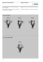
Bauarten / Drehrichtungen Design / Direction Ein- und Abtriebswellen sind mit den Drehrichtungen von- The directions from input- and output shaft are interdepen- einander abhangig. dent. Die verschiedenen Moglichkeiten sind an den nachfolgen- The different possibilities you can see on the design below.
Open the catalog to page 8
Seitenbezeichnungen / Drehrichtungen Identification of sides / Directions of rotation Um ein Kegelstirnradgetriebe genau definieren und beschreiben zu können sind einheitliche Standards notwendig. Wichtig hierzu ist die Bezeichnung der einzelnen Seiten der Getriebe, sowie die Lage der Kegelräder / Stirnräder und die genaue Definition der Drehrichtungen. To describe and define a helical bevel-gearbox accurately, uniform standards are required. The important points here are a way of identifying each side of a gearbox and the positions of the bevel gears, and clear definition of the directions of...
Open the catalog to page 9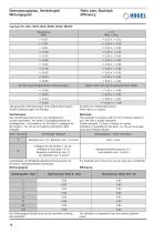
Übersetzungsplan, Verdrehspiel Wirkungsgrad Ratio plan, Backlash Efficiency Typ/Type KS, KSH, KSHF, MKS, MKSH, MKSF, MKSHF Übersetzung Ratio Ab hier Hypoid-Kegelradsatz mit Achsversatz Higher ratios with hypoid gearset (pinion offset) i = 48,00 Alle genannten Übersetzungen sind mathematisch genau. Andere Übersetzungen auf Anfrage. i = 10,00 x i = 4,80 All ratios are mathematical exact. Other ratios on request. Das Verdrehspiel wird mit 2% vom Getriebenennmoment gemessen. Wir bieten 2 Qualitätsstandards an. Qualitätsstufe 1 ist kostenlos, für die Stufe 2 (verfügbar für die Größen 1 bis 16) ist...
Open the catalog to page 10
Achtung! Bitte Kapitel Wärmegrenzleistung beachten. Attention! See chapter Thermal rating. Bei der Berechnung der max. geforderten Einsatzleistung P der anzutreibenden Maschine müssen folgende Einsatzbedingungen beachtet werden: c1 = Stossfaktor in Abhängigkeit von der Anzahl der Anläufe pro Stunde und der Betriebsdauer c2 = Umgebungstemperatur Die geforderte Eingangsleistung P errechnet sich wie folgt: When calculating the maximum required input power P of the machine to be driven, the following application conditions have to be observed: c1 = Shock factor - this depends on the “starts per hour”...
Open the catalog to page 11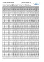
Selecting the right size Die vorgesehene Betriebsart ist S5. Bei anderen Betriebsarten bitten wir um Rücksprache. The planned operating mode is S5. Please contact us if you intend to use other operating modes. Antriebsdrehz. Input speed Abtriebsdrehz. Output speed KS 4 KS 8 KS 16 KS 32 Abtriebsdrehmoment / Nominal output torque P T2 P T2 P T2 P T2 KW Nm KW Nm KW Nm KW Nm
Open the catalog to page 12All VOGEL catalogs and technical brochures
 Mechanical-Getriebe
152 Pages
 2018 Servo gearboxes
72 Pages
 Rack & Pinion Drive_2013
44 Pages
 Mechanical gearboxes
152 Pages
 Industrial gearboxes
164 Pages
 Image brochure english
14 Pages
 Motor mounting
2 Pages
 Spiral bevel gearboxes
76 Pages
 Planetary gearboxes
80 Pages
 Phase shifter gearboxes
36 Pages


Archived catalogs
 Rack & Pinion Drive_2012
40 Pages
 2014 Servo gearboxes
140 Pages
 WELCOME TO VOGEL ANTRIEBSTECHNIK
14 Pages
- Planetary gearbox
- Coaxial gearhead
- Precision gearhead
- Right angle gearhead
- Compact gearhead
- Gear train gear reducer
- Shaft gearhead
- Helical gear gearhead
- Low-backlash gearhead
- Bevel gearhead
- Servo-gearbox
- Spur gearhead
- Waterproof gear reducer
- Planetary servo-gearbox
- IP65 gear reducer
- Spiral bevel gear reducer
- Precision servo-gearbox
- Coaxial servo-gearbox
- Universal gear reducer
- Right angle servo-gearbox