- Catalogs
- Vision Components
- VCSBC Quadro
VCSBC Quadro
1 /21Pages

VCSBC Quadro
1 /21Pages
Catalog excerpts

Vision ® Components The Smart Camera People VCSBC Quadro Single Board Operating Manual Hardware specifications and special software functions of SBC Quadro Single Board Smart Camera Revision 1.0 preliminary – 16 Apr 2013 Document name: VCSBCQuadro.pdf Vision Components GmbH Ettlingen, Germany
Open the catalog to page 1
VCSBC nano Single Board Smart Cameras Operating Manual Foreword and Disclaimer This documentation has been prepared with most possible care. However Vision Components GmbH does not take any liability for possible errors. In the interest of progress, Vision Components GmbH reserves the right to perform technical changes without further notice. Please notify [email protected] if you become aware of any errors in this manual or if a certain topic requires more detailed documentation. This manual is intended for information of Vision Component’s customers only. Any publication of this...
Open the catalog to page 2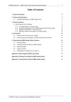
VCSBCQuadro.pdf – VCSBC Quadro Smart Camera Operating Manual Table of Contents 1 General Information Technical Specifications VCSBC Quadro 6210 3 Camera Interfaces J1: Power Supply and IO Interface 3.1.1 3.1.2 3.1.3 3.1.4 Pin Assignments J1 camera socket Electrical specifications of the VCSBC Quadro Series Power Supply Electrical specifications J1 camera socket Matching connector and cable for J2 camera socket Camera and Lens holder order numbers: Further accessories available for VCSBC Quadro Smart Cameras 5 Programming VCSBC Quadro Smart Cameras General settings Compiling and linking with the...
Open the catalog to page 3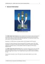
VCSBCQuadro.pdf – VCSBC Quadro Smart Camera Operating Manual VCSBC Quadro Smart Camera The VCSBC Quadro Smart Camera have been designed for high resolution image processing with a very small form factor. They are the ideal compromise between high performance and low system costs, and thus especially suited for high volume OEM applications. This makes them viable to use a smart camera in even more products than before. Employing 1 to 4 CMOS sensors, the image resolution can be changed to the ROI required. Like with all VC Smart Cameras with Texas Instruments DSP, the operation system VCRT allows...
Open the catalog to page 4
VCSBCQuadro.pdf – VCSBC Quadro Smart Camera Operating Manual Technical Specifications VCSBC Quadro 6210 Component / Feature CMOS Sensor: 4x 1/3" Aptina MT9V034 - also available with color sensor (Bayer Filter) Pixel size: Chip size: High-speed shutter: Low-speed shutter: up to 2 sec. adjustable integration time Global shutter Picture taking: program-controlled or external high speed trigger, full-frame (55 frames per second) & partial scanning, jitterfree acquisition Parallel image acquisition 27 MHz / 10 bit, only the 8 most significant bits used for grey values Image Display Via 100 Mbit Ethernet...
Open the catalog to page 5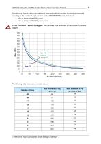
VCSBCQuadro.pdf – VCSBC Quadro Smart Camera Operating Manual The following diagram shows the maximum reachable (with the shortest shutter time) framerate according to the number of captured lines for the VCSBC6210 Quadro, in 2 cases: - with an image width of 752 pixels - with an image width of 640 pixels or less Values are valid if 1 sensor is plugged! The framerate must be divided by the number of sensors plugged. The following table gives some example values. 1996-2013 Vision Components GmbH Ettlingen, Germany
Open the catalog to page 6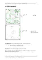
VCSBCQuadro.pdf – VCSBC Quadro Smart Camera Operating Manual J1 BOTTOM SIDE (J1 connector side) The VCSBC Quadro Series camera board incorporates one connector interfaces: J 1: Power, IO, Ethernet and RS232 Connector The SBC Quadro series are available with one to four sensor heads. The pin assignments, electrical specifications as well as available accessories are shown for each interface connector in the following sections. 1996-2013 Vision Components GmbH Ettlingen, Germany
Open the catalog to page 7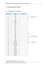
VCSBCQuadro.pdf – VCSBC Quadro Smart Camera Operating Manual J1: Power Supply and IO Interface Pin Assignments J1 camera socket Core Color According to matching Power / PLC Cable VK000173 1996-2013 Vision Components GmbH Ettlingen, Germany Ethernet interface
Open the catalog to page 8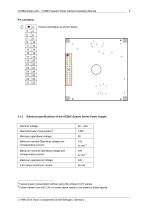
VCSBCQuadro.pdf – VCSBC Quadro Smart Camera Operating Manual If board orientation as shown below: Electrical specifications of the VCSBC Quadro Series Power Supply Nominal Voltage: Nominal Power Consumption : Minimum operational voltage: Maximum nominal Operating voltage and corresponding current: Maximum operational Voltage: 3.3V output maximum current Minimum nominal Operating voltage and corresponding current: Typical power consumption without using the onboard 3.3V supply. Current drawn from the 3.3V on board signal needs to be added to these figures. 1996-2013 Vision Components GmbH Ettlingen,...
Open the catalog to page 9
VCSBCQuadro.pdf – VCSBC Quadro Smart Camera Operating Manual Camera power is regulated, so only an unregulated power source of 12 V to 24V is required. The camera is, however, very sensitive to power supply interruption. Please make sure, that the voltage never exceeds the limits of < 9V, > 30V even for a short period of time. In case of trouble it is recommended to backup the power supply by a capacitor or a battery large enough to prevent power interruptions. Electrical specifications J1 camera socket All Signals are Low Level CMOS (3.3V), not opto isolated (so special care must be taken or...
Open the catalog to page 10
VCSBCQuadro.pdf – VCSBC Quadro Smart Camera Operating Manual Please note that input and output are not protected against over current. The output is neither protected against short circuit nor reverse voltage spikes from inductive loads. Use the VC nano Series cameras if you can not provide a suitable trigger input driving circuit. These cameras include the same hardware as the VCSBC nano Series Smart Cameras, but overcurrent protection of the inputs and outputs is already included. 1996-2013 Vision Components GmbH Ettlingen, Germany
Open the catalog to page 11
VCSBCQuadro.pdf – VCSBC Quadro Smart Camera Operating Manual Possible driving circuit for the LVCMOS inputs (also trigger input): Camera side: Pin 3 Trig In Electrical Specification of trigger output : output voltage signal LOW: 0.4 V with 2mA output current 0.2 V with 1mA output current output voltage signal HIGH: 2.9 V with 8mA output current 3.1 V with 1mA output current max. 3 V LVTTL Maximum output current: pull-up resistor: none, LVTTL push-pull output Caution: Place the connectors at the correct position – not reversed or shifted. Possible driving circuit for LVCMOS outputs (also trigger...
Open the catalog to page 12All Vision Components catalogs and technical brochures
 flyer MIPI Camera Modules
2 Pages
 VC4067NIR_EL_E_Euro
1 Page
 VC4019
2 Pages
 VC4018
1 Page
 VC-SmartCameras
20 Pages
 Vision Components
11 Pages
 VC4438
1 Page
 VC4038
1 Page
 VC4016
1 Page
 VC nano3D
1 Page
 VC6210nano
1 Page
 VC4012nano
2 Pages
 VCnano SmartCameras
2 Pages

Archived catalogs
 VC_all_products
16 Pages
 VisiCube
1 Page
 VCLine
1 Page
 VCBoardCam family
3 Pages
 VCProfessional+Base family
8 Pages
 VCOptimum family
6 Pages
- Liebherr digital camera
- Liebherr visible camera
- CMOS camera module
- Liebherr industrial camera
- Liebherr infrared camera
- Liebherr monitoring camera
- Full-color camera system
- Liebherr detection camera
- Image processing camera module
- Monochrome camera module
- GigE Vision camera
- Liebherr waterproof camera
- Liebherr compact camera
- Liebherr rugged video camera
- High-speed camera module
- Camera with global shutter
- Liebherr high-performance camera
- Laboratory camera module
- Liebherr Ethernet camera