

- Products
- Catalogs
- News & Trends
- Exhibitions
VS-E5PX3006LHN3

VS-E5PX3006LHN3
- Hyperfast recovery with optimized Qrr.
- Low forward voltage drop and switching losses.
- Maximum operating junction temperature of 175°C.
- Polyimide passivation and AEC-Q101 qualification.
- Average forward current (IF(AV)): 30 A
- Repetitive peak reverse voltage (VRRM): 600 V
- Forward voltage (VF) at 125°C: 1.3 V
- Maximum junction temperature (TJ max.): 175°C
- Repetitive peak reverse voltage: 600 V
- Average rectified forward current: 30 A
- Non-repetitive peak surge current: 310 A
- Operating junction and storage temperature range: -55 to +175°C
Catalog excerpts

Vishay Semiconductors Hyperfast Rectifier, 30 A FRED Pt® G5 FEATURES Base cathode • Best in class forward voltage drop and switching losses trade off • Optimized for high speed operation • 175 °C maximum operating junction temperature • Polyimide passivation • AEC-Q101 qualified meets JESD 201 class 1A whisker test • Material categorization: for definitions of compliance please see www.vishay.com/doc?99912 PRIMARY CHARACTERISTICS IF(AV) DESCRIPTION / APPLICATIONS Featuring a unique combination of low conduction and switching losses, this rectifier is the right choice for soft switched and resonant converters, as well as medium frequency hard switching converters. This device is specifically designed to improve efficiency of high speed LLC output rectification stages of EV / HEV on-board battery chargers Circuit configuration MECHANICAL DATA LINKS TO ADDITIONAL RESOURCES Case: TO-247AD 2L Molding compound meets UL 94 V-0 flammability rating Terminal: matte tin plated leads, solderable per J-STD-002 ABSOLUTE MAXIMUM RATINGS PARAMETER TEST CONDITIONS Repetitive peak reverse voltage Average rectified forward current Non-repetitive peak surge current Repetitive peak forward current Operating junction and storage temperature ELECTRICAL SPECIFICATIONS (TJ = 25 °C unless otherwise specified) PARAMETER Breakdown voltage, blocking voltage SYMBOL VBR,VR Forward voltage Reverse leakage current Junction capacitance Series inductance TEST CONDITIONS Measured to lead 5 mm from package body Revision: 17-Mar-2021 Document Number: 96810 1 For technical questions within your region: [email protected], [email protected], [email protected] THIS DOCUMENT IS SUBJECT TO CHANGE WITHOUT NOTICE. THE PRODUCTS DESCRIBED HEREIN AND THIS DOCUMENT ARE SUBJECT TO SPECIFIC DISCLAIMERS, SET FORTH AT
Open the catalog to page 1
Vishay Semiconductors DYNAMIC RECOVERY CHARACTERISTICS (TJ = 25 °C unless otherwise specified) PARAMETER TEST CONDITIONS IF = 1.0 A, dIF/dt = 100 A/μs, VR = 30 V Reverse recovery time Peak recovery current Reverse recovery charge Peak recovery current Reverse recovery time Reverse recovery charge THERMAL - MECHANICAL SPECIFICATIONS PARAMETER Thermal resistance, junction-to-case TEST CONDITIONS Weight Mounting torque Maximum junction and storage temperature range TJ, TStg Case style: TO-247AD 2L IF - Instantaneous Forward Current (A) Marking device VF - Forward Voltage Drop (V) Fig. 1 - Typical...
Open the catalog to page 2
Allowable Solder Pad Temperature (°C) Vishay Semiconductors 140 130 120 110 Square wave (D = 0.50) rated VR applied IF(AV) - Average Forward Current (A) Fig. 3 - Typical Junction Capacitance vs. Reverse Voltage Fig. 4 - Maximum Allowable Case Temperature vs. Average Forward Current Average Power Loss (W) IF(AV) - Average Forward Current (A) Fig. 5 - Average Power Loss vs. Average Forward Current ZthJC - Thermal Impedance Junction to Case (°C/W) t1 - Rectangular Pulse Duration (s) Fig. 6 - Thermal Impedance ZthJC - Characteristics Revision: 17-Mar-2021 Document Number: 96810 3 For technical questions...
Open the catalog to page 3
Vishay Semiconductors In this dI/dt range curves are not dependent from applied IF switching current, from 0.5 to 2 times IF(AV) rating Fig. 7 - Typical Reverse Recovery Time vs. dIF/dt Fig. 10 - Typical Reverse Recovery Time vs. dIF/dt In this dI/dt range curves are not dependent from applied IF switching current, from 0.5 to 2 times IF(AV) rating Fig. 8 - Typical Reverse Recovery Charge vs. dIF/dt Fig. 11 - Typical Reverse Recovery Charge vs. dIF/dt In this dI/dt range curves are not dependent from applied IF switching current, from 0.5 to 2 times IF(AV) rating Fig. 9 - Typical Reverse Recovery...
Open the catalog to page 4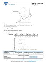
Fig. 13 - Reverse Recovery Waveform and Definitions Notes (1) di /dt - rate of change of current through zero crossing F (2) I RRM - peak reverse recovery current (3) t - reverse recovery time measured from t , crossing point of negative going I , to point t rr 0 F 10%, 0.1 IRRM (4) Q - area under curve defined by t and t rr 0 10 % t 10 % di(rec)M/dt - peak rate of change of current during tb portion of trr ORDERING INFORMATION TABLE Device code Vishay Semiconductors product Circuit configuration E = single diode FRED Pt® Gen 5 P = TO-247 package Process type: X = hyperfast recovery Current rating...
Open the catalog to page 5
Legal Disclaimer Notice www.vishay.com Disclaimer ALL PRODUCT, PRODUCT SPECIFICATIONS AND DATA ARE SUBJECT TO CHANGE WITHOUT NOTICE TO IMPROVE RELIABILITY, FUNCTION OR DESIGN OR OTHERWISE. Vishay Intertechnology, Inc., its affiliates, agents, and employees, and all persons acting on its or their behalf (collectively, “Vishay”), disclaim any and all liability for any errors, inaccuracies or incompleteness contained in any datasheet or in any other disclosure relating to any product. Vishay makes no warranty, representation or guarantee regarding the suitability of the products for any particular...
Open the catalog to page 6All VISHAY catalogs and technical brochures
 VS-E5TH1506THN3
8 Pages
 VS-E5TX1506THN3
8 Pages
 VS-E5TH3006THN3
8 Pages
 VS-E5TX3006THN3
8 Pages
 VS-E5PH3006LHN3
6 Pages
 VS-E5PH6006LHN3
6 Pages
 VS-E5PX6006LHN3
6 Pages
 VS-E5PH7506LHN3
6 Pages
 VS-E5PX7506LHN3
6 Pages
 VCNL36825T
16 Pages
 VS-E5TH1506-M3
7 Pages
 VS-E5TX1506-M3
7 Pages
 VS-E5TH3006-M3
7 Pages
 VS-E5TX3006-M3
7 Pages
 VS-E5PH3006L-N3
8 Pages
 VS-E5PX3006L-N3
7 Pages
 VS-E5PH6006L-N3
7 Pages
 VS-E5PX6006L-N3
7 Pages
 VS-E5PH7506L-N3
7 Pages
 VS-E5PX7506L-N3
7 Pages
 VS-C04ET07T-M3
5 Pages
 VS-C06ET07T-M3
5 Pages
 VS-C08ET07T-M3
5 Pages
 VS-C10ET07T-M3
5 Pages
 VS-C12ET07T-M3
5 Pages
 VS-C16CP07L-M3
5 Pages
 VS-C16ET07T-M3
5 Pages
 VS-C20CP07L-M3
5 Pages
 VS-C20ET07T-M3
5 Pages
 VS-C40CP07L-M3
5 Pages
 P11H
P11H7 Pages
 IHTH-1500MZ-5A
4 Pages
 IHTH-1500TZ-5A
4 Pages
 MFU AT SERIES
8 Pages
 T24
T247 Pages
 CRHA
CRHA4 Pages
 IHXL-1500VZ-5A
5 Pages
 Power Modules
32 Pages
 Bare Die
29 Pages
 TMBS® Rectifiers
2 Pages
 XOSM-531 OSCILLATORS
3 Pages
 IHLP2525EZ-01 INDUCTORS
4 Pages
 HYBRIDS & SUBSTRATES HP - MT
2 Pages
 Fuses HCTF CP Series
5 Pages
 XT49S CRYSTALS
3 Pages
 VOM1271 SOLID-STATE RELAYS
7 Pages
 Si5904DC MOSFETS
9 Pages
 Chip Antenna
6 Pages
 2381 691 90001/HUMIDITY-SENS-E
2 Pages
 Inductors - Power Inductors
2 Pages
 Capacitors - Ceramic
7 Pages
 Capacitors - Radial
5 Pages


Archived catalogs
 RC Thermal Model for 2N7002K
3 Pages
 MLCC Product Road Map
4 Pages


- Connector
- Display module
- Transformer
- Angular encoder
- Proximity switch
- Switching relay
- Rectangular connector
- Capacitor
- Inductive proximity sensor
- LED display panel
- Absolute rotary encoder
- Position transducer
- Electronic display panel
- Power transformer
- Transceiver module
- Industrial rotary encoder
- Linear position transmitter
- Magnetic rotary encoder
- Medical equipment display
- Radio antenna