VOM1271 SOLID-STATE RELAYS
1 /7Pages

VOM1271 SOLID-STATE RELAYS
1 /7Pages
Catalog excerpts

Vishay Semiconductors Photovoltaic MOSFET Driver with Integrated Fast Turn-Off, Solid-State Relay FEATURES • Open circuit voltage at IF = 10 mA, 8.4 V typical 1 • Short circuit current at IF = 10 mA, 15 μA typical • Isolation test voltage 4500 VRMS • Logic compatible input • High reliability • Integrated rapid turn-off circuitry • Material categorization: For definitions of compliance please see www.vishay.com/doc?99912 APPLICATIONS • High-side driver • Solid-state relays The VOM1271 is a stand-alone optically isolated MOSFET driver. Unlike conventional MOSFET drivers, which require an external power supply to provide VCC and or VDD rails to the driver itself, the VOM1271 obtains all the required current to drive its internal circuitry from the LED current on the low voltage primary side of the isolation barrier. This saves the designer the space and cost associated with providing one or more external power supplies. The VOM1271 also integrates a turn-off circuit internal to the component itself, thus doing away with the need for additional components in order to increase the overall switching speed by decreasing the turn-off time. These features, combined with a small SOP4 package, provide designers with a small footprint, highly integrated isolated gate driver solution for a large variety of MOSFET drive applications. • Floating power supply • Power control • Data acquisition • ATE • Isolated solenoid drivers • Isolated high current relay drivers • Isolated high voltage relay drivers AGENCY APPROVALS • UL1577 • cUL, equivalent to CSA bulletin 5A • FIMKO EN 60950-1 SAFETY AGENCY COMPLIANCE Please see document: www.vishay.com/doc?83743 Note • For additional information on the available options refer to option information. The product is available only on tape and reel. Document Number: 83469 1 For technical questions, contact: [email protected] THIS DOCUMENT IS SUBJECT TO CHANGE WITHOUT NOTICE. THE PRODUCTS DESCRIBED HEREIN AND THIS DOCUMENT ARE SUBJECT TO SPECIFIC DISCLAIMERS, SET FORTH AT www.vishay.com/doc?91000
Open the catalog to page 1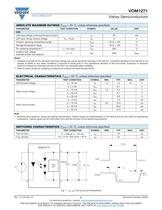
Vishay Semiconductors ABSOLUTE MAXIMUM RATINGS (Tamb = 25 °C, unless otherwise specified) PARAMETER TEST CONDITION SSR LED input ratings continous forward current LED input ratings reverse voltage Ambient operating temperature range Storage temperature range Isolation test voltage between emitter and detector Notes • Stresses in excess of the absolute maximum ratings can cause permanent damage to the device. Functional operation of the device is not implied at these or any other conditions in excess of those given in the operational sections of this document. Exposure to absolute maximum ratings...
Open the catalog to page 2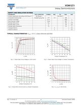
Vishay Semiconductors SAFETY AND INSULATION RATINGS PARAMETER TEST CONDITION Climatic classification (according to IEC 68 part 1) Comparative tracking index IEC 68 part 1 Insulation group IIIa Transient overvoltage Recurring peak voltage Package safety power Package safety current Package safety temperature Creepage distance Clearance distance TYPICAL CHARACTERISTICS (Tamb = 25 °C, unless otherwise specified) 12 Fig. 2 - Output Open Circuit Voltage vs. LED Current Fig. 4 - Output Open Circuit Voltage vs. Ambient Temperature Ambient Temperature (°C) Fig. 3 - Output Short-Circuit Current vs. Ambient...
Open the catalog to page 3
Vishay Semiconductors ISC - Short Circuit Output Current (μA) VOC - Open Circuit Output Voltage (V) Fig. 6 - LED Reverse Current vs. Reverse Voltage Fig. 8 - Short Circuit Output Current vs. Open Circuit Output Voltage IF (mA) Fig. 7 - LED Forward Voltage vs. LED Forward Current APPLICATION DESCRIPTION Figure 8 illustrates a standard isolated MOSFET driver such as Vishay’s VO1263. Though these parts are generally capable of supplying higher output current, they lack integrated fast turn-off circuitry. Thus, if high turn-off speed is required. external circuitry needs to be provided, as illustrated...
Open the catalog to page 4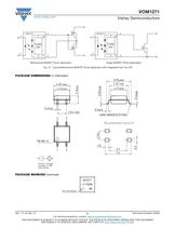
Vishay Semiconductors Bidirectional MOSFET Driver Application Single MOSFET Driver Application Fig. 10 - Typical Bidirectional MOSFET Driver Application with Integrated Fast Turn-Off PACKAGE DIMENSIONS in millimeters technical drawings Recommended footprint PACKAGE MARKING (example) For technical questions, contact: [email protected] THIS DOCUMENT IS SUBJECT TO CHANGE WITHOUT NOTICE. THE PRODUCTS DESCRIBED HEREIN AND THIS DOCUMENT ARE SUBJECT TO SPECIFIC DISCLAIMERS, SET FORTH AT www.vishay.com/doc791000
Open the catalog to page 5
Vishay Semiconductors TAPE AND REEL PACKAGING Regular, special Fig. 11 - Tape and Reel Shipping Medium (EIA-481, revision A, and IEC 60286), 2000 units per reel For technical questions, contact: [email protected] THIS DOCUMENT IS SUBJECT TO CHANGE WITHOUT NOTICE. THE PRODUCTS DESCRIBED HEREIN AND THIS DOCUMENT ARE SUBJECT TO SPECIFIC DISCLAIMERS, SET FORTH AT www.vishay.com/doc791000
Open the catalog to page 6
Legal Disclaimer Notice www.vishay.com Disclaimer ALL PRODUCT, PRODUCT SPECIFICATIONS AND DATA ARE SUBJECT TO CHANGE WITHOUT NOTICE TO IMPROVE RELIABILITY, FUNCTION OR DESIGN OR OTHERWISE. Vishay Intertechnology, Inc., its affiliates, agents, and employees, and all persons acting on its or their behalf (collectively, “Vishay”), disclaim any and all liability for any errors, inaccuracies or incompleteness contained in any datasheet or in any other disclosure relating to any product. Vishay makes no warranty, representation or guarantee regarding the suitability of the products for any particular...
Open the catalog to page 7All VISHAY catalogs and technical brochures
 VS-E5TH1506THN3
8 Pages
 VS-E5TX1506THN3
8 Pages
 VS-E5TH3006THN3
8 Pages
 VS-E5TX3006THN3
8 Pages
 VS-E5PH3006LHN3
6 Pages
 VS-E5PX3006LHN3
6 Pages
 VS-E5PH6006LHN3
6 Pages
 VS-E5PX6006LHN3
6 Pages
 VS-E5PH7506LHN3
6 Pages
 VS-E5PX7506LHN3
6 Pages
 VCNL36825T
16 Pages
 VS-E5TH1506-M3
7 Pages
 VS-E5TX1506-M3
7 Pages
 VS-E5TH3006-M3
7 Pages
 VS-E5TX3006-M3
7 Pages
 VS-E5PH3006L-N3
8 Pages
 VS-E5PX3006L-N3
7 Pages
 VS-E5PH6006L-N3
7 Pages
 VS-E5PX6006L-N3
7 Pages
 VS-E5PH7506L-N3
7 Pages
 VS-E5PX7506L-N3
7 Pages
 VS-C04ET07T-M3
5 Pages
 VS-C06ET07T-M3
5 Pages
 VS-C08ET07T-M3
5 Pages
 VS-C10ET07T-M3
5 Pages
 VS-C12ET07T-M3
5 Pages
 VS-C16CP07L-M3
5 Pages
 VS-C16ET07T-M3
5 Pages
 VS-C20CP07L-M3
5 Pages
 VS-C20ET07T-M3
5 Pages
 VS-C40CP07L-M3
5 Pages
 P11H
P11H7 Pages
 IHTH-1500MZ-5A
4 Pages
 IHTH-1500TZ-5A
4 Pages
 MFU AT SERIES
8 Pages
 T24
T247 Pages
 CRHA
CRHA4 Pages
 IHXL-1500VZ-5A
5 Pages
 Power Modules
32 Pages
 Bare Die
29 Pages
 TMBS® Rectifiers
2 Pages
 XOSM-531 OSCILLATORS
3 Pages
 IHLP2525EZ-01 INDUCTORS
4 Pages
 HYBRIDS & SUBSTRATES HP - MT
2 Pages
 Fuses HCTF CP Series
5 Pages
 XT49S CRYSTALS
3 Pages
 Si5904DC MOSFETS
9 Pages
 Chip Antenna
6 Pages
 2381 691 90001/HUMIDITY-SENS-E
2 Pages
 Inductors - Power Inductors
2 Pages
 Capacitors - Ceramic
7 Pages
 Capacitors - Radial
5 Pages


Archived catalogs
 RC Thermal Model for 2N7002K
3 Pages
 MLCC Product Road Map
4 Pages


- Connector
- Display module
- Proximity switch
- Rectangular connector
- Switching relay
- Capacitor
- LED display panel
- Position transducer
- Inductive proximity sensor
- Transceiver module
- Electronic display panel
- Linear position transmitter
- Radio antenna
- Analog position transducer
- SMT connector
- Diode
- No-contact position sensor
- Medical equipment display
- Potentiometer
- Ceramic capacitor