VJ....32 Lead-Bearing Finish MLCCs
1 /21Pages

VJ....32 Lead-Bearing Finish MLCCs
1 /21Pages
Catalog excerpts

Vishay Vitramon Surface Mount Multilayer Ceramic Chip Capacitors With Lead-Bearing Finish Termination FEATURES • Tin / lead termination finish - minimum 4 % lead • Available in 0402 to 1210 body size • Two dielectrics • High operating temperature, high reliability • Wet build process • Reliable Noble Metal Electrode (NME) system • AEC-Q200 qualified with PPAP available • Custom combinations to meet specific need • Material categorization: for definitions of compliance please see www.vishay.com/doc?99912 Low earth orbit satellites (LEO) Space Aerospace Avionic Military Tin whisker mitigation ELECTRICAL SPECIFICATIONS C0G (NP0) DIELECTRIC Note Electrical characteristics at +25 °C unless otherwise specified Note Electrical characteristics at +25 °C unless otherwise specified Operating Temperature: -55 °C to +150 °C (above +125 °C changed characteristics) Operating Temperature: -55 °C to +150 °C (above +125 °C changed characteristics) Temperature Coefficient of Capacitance (TCC): 0 ppm/°C ± 30 ppm/°C from -55 °C to +125 °C Temperature Coefficient of Capacitance (TCC): ± 15 % from -55 °C to +125 °C, with 0 VDC applied Dissipation Factor (DF): 0.1 % maximum at 1.0 VRMS and 1 MHz for values 1000 pF 0.1 % maximum at 1.0 VRMS and 1 kHz for values > 1000 pF Dissipation Factor (DF): 16 V, 25 V ratings: 3.5 % maximum at 1.0 VRMS and 1 kHz > 25 V ratings: 2.5 % maximum at 1.0 VRMS and 1 kHz Insulating Resistance: at +25 °C 100 000 M min. or 1000 F whichever is less at +125 °C 10 000 M min. or 100 F whichever is less Aging: 0 % maximum per decade Dielectric Strength Test: performed per method 103 of EIA 198-2-E. Applied test voltages 250 VDC-rated: 250 % of rated voltage 500 VDC-rated: 200 % of rated voltage 630 VDC-rated: 150 % of rated voltage GENERAL SPECIFICATION Insulating Resistance: at +25 °C 100 000 M min. or 1000 F whichever is less at +125 °C 10 000 M min. or 100 F whichever is less Aging Rate: 1 % maximum per decade Dielectric Strength Test: performed per method 103 of EIA 198-2-E. Applied test voltages 250 % of rated voltage 250 VDC-rated: 500 VDC-rated: min. 150 % of rated voltage 630 VDC-rated: min. 120 % of rated voltage Note (1) Under qualification; contact factory for availability Document Number: 45256 1 For technical questions, contact: [email protected] THIS DOCUMENT IS SUBJECT TO CHANGE WITHOUT NO
Open the catalog to page 1
Vishay Vitramon QUICK REFERENCE DATA DIELECTRIC CASE CODE Note • Detail ratings see “Selection Chart” CASE CODE DIELECTRIC CAPACITANCE NOMINAL CODE CAPACITANCE TOLERANCE A, D = Expressed in B = ± 0.10 pF C0G (NP0) (2) picofarads (pF). C = ± 0.25 pF Y = X7R The first two D = ± 0.5 pF digits are F=±1% significant, the G=±2% third is a J=±5% multiplier. An K = ± 10 % “R” indicates a M = ± 20 % decimal point. Note Examples C0G (NP0): 4R7 = 4.7 pF B, C, D < 10 pF 102 = 1000 pF F, G, J, K 10 pF X7R: J, K, M TERMINATION DC VOLTAGE RATING (1) L = Ni barrier with tin lead plated finish min. 4 % lead...
Open the catalog to page 2
Vishay Vitramon SELECTION CHART DIELECTRIC CASE CODE VOLTAGE (VDC) VOLTAGE CODE
Open the catalog to page 3
Vishay Vitramon SELECTION CHART DIELECTRIC CASE CODE VOLTAGE (VDC) VOLTAGE CODE Note •• Paper tape, • Plastic tape Document Number: 45256 4 For technical questions, contact: [email protected] THIS DOCUMENT IS SUBJECT TO CHANGE WITHOUT NOTICE. THE PRODUCTS DESCRIBED HEREIN AND THIS DOCUMENT ARE SUBJECT TO SPECIFIC DISCLAIMERS,
Open the catalog to page 4
Vishay Vitramon SELECTION CHART DIELECTRIC CASE CODE VOLTAGE CODE
Open the catalog to page 5
Vishay Vitramon SELECTION CHART DIELECTRIC CASE CODE VOLTAGE CODE Note •• Paper tape, • Plastic tape Document Number: 45256 6 For technical questions, contact: [email protected] THIS DOCUMENT IS S
Open the catalog to page 6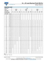
Vishay Vitramon SELECTION CHART DIELECTRIC CASE CODE VOLTAGE (VDC) VOLTAGE CODE
Open the catalog to page 7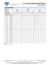
Vishay Vitramon SELECTION CHART DIELECTRIC CASE CODE VOLTAGE (VDC) VOLTAGE CODE CAP. CODE Note •• Paper tape, • Plastic tape Document Number: 45256 8 For technical questions, contact: [email protected] THIS DOCUMENT IS SUBJECT TO CHANGE WITHOUT NOTICE. THE PRODUCTS DESCRIBED HEREIN AND THIS DOCUMENT ARE
Open the catalog to page 8
Vishay Vitramon SELECTION CHART DIELECTRIC CASE CODE VOLTAGE CODE
Open the catalog to page 9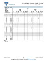
Vishay Vitramon SELECTION CHART DIELECTRIC VOLTAGE CODE CAP. CODE CASE CODE Note • Plastic tape Document Number: 45256 10 For technical questions
Open the catalog to page 10
Vishay Vitramon STANDARD PACKAGING QUANTITIES (1)(2) 7" REEL QUANTITIES CASE CODE TAPE SIZE PAPER TAPE PLASTIC TAPE LOW QUANTITY PAPER TAPE PLASTIC TAPE PACKAGING CODE PACKAGING CODE PACKAGING CODE PACKAGING CODE PACKAGING CODE “C” “T” “J” “P” “R” Notes (1) Reference: EIA standard RS 481 - “Taping of Surface Mount Components for Automatic Placement” (2) n/a = not available (3) Packaging quantity can depend from product thickness Document Number: 45256 11 For technical questions, contact: [email protected] THIS DOCUMENT IS SUBJECT TO CHANGE WITHOUT NOTICE. THE PRODUCTS DESCRIBED HEREIN AND THIS...
Open the catalog to page 11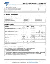
Vishay Vitramon 1 - GENERAL CERTIFICATES # Quality management system according to IATF 16949 # Quality management system according to ISO 9001 # Environmental certification according to ISO 14001 # Health and safety system according to ISO 45001 2 - TECHNICAL REQUIREMENTS Unless specified in component specification, these parameters are the minimum requirements for the components. 2.1 OPERATING TEMPERATURE RANGE For standard applications For high temperature applications For ultra high temperature applications 2.2 CHARACTERISTICS PARAMETER Rated voltage in temperature range -55 °C to +125 °C...
Open the catalog to page 12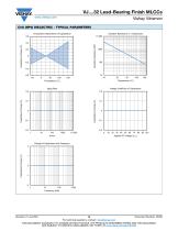
Vishay Vitramon C0G (NP0) DIELECTRIC - TYPICAL PARAMETERS Temperature Dependence of Capacitance Insulation Resistance vs. Temperature 10000 2nd line Insulation Resistance (ΩF) 2nd line Capacitance Change (%) 2nd line Capacitance Change (%) 2nd line Capacitance Change (%) Voltage Coefficient of Capacitance Change of Capacitance with Frequency 10000 2nd line Capacitance Change (%) Document Number: 45256 13 For technical questions, contact: [email protected] THIS DOCUMENT IS SUBJECT TO CHANGE WITHOUT NOTICE. THE PRODUCTS DESCRIBED HEREIN AND THIS DOCUMENT ARE SUBJECT TO SPECIFIC DISCLAIMERS, SET FORTH...
Open the catalog to page 13All VISHAY catalogs and technical brochures
 VS-E5TH1506THN3
8 Pages
 VS-E5TX1506THN3
8 Pages
 VS-E5TH3006THN3
8 Pages
 VS-E5TX3006THN3
8 Pages
 VS-E5PH3006LHN3
6 Pages
 VS-E5PX3006LHN3
6 Pages
 VS-E5PH6006LHN3
6 Pages
 VS-E5PX6006LHN3
6 Pages
 VS-E5PH7506LHN3
6 Pages
 VS-E5PX7506LHN3
6 Pages
 VCNL36825T
16 Pages
 VS-E5TH1506-M3
7 Pages
 VS-E5TX1506-M3
7 Pages
 VS-E5TH3006-M3
7 Pages
 VS-E5TX3006-M3
7 Pages
 VS-E5PH3006L-N3
8 Pages
 VS-E5PX3006L-N3
7 Pages
 VS-E5PH6006L-N3
7 Pages
 VS-E5PX6006L-N3
7 Pages
 VS-E5PH7506L-N3
7 Pages
 VS-E5PX7506L-N3
7 Pages
 VS-C04ET07T-M3
5 Pages
 VS-C06ET07T-M3
5 Pages
 VS-C08ET07T-M3
5 Pages
 VS-C10ET07T-M3
5 Pages
 VS-C12ET07T-M3
5 Pages
 VS-C16CP07L-M3
5 Pages
 VS-C16ET07T-M3
5 Pages
 VS-C20CP07L-M3
5 Pages
 VS-C20ET07T-M3
5 Pages
 VS-C40CP07L-M3
5 Pages
 P11H
P11H7 Pages
 IHTH-1500MZ-5A
4 Pages
 IHTH-1500TZ-5A
4 Pages
 MFU AT SERIES
8 Pages
 T24
T247 Pages
 CRHA
CRHA4 Pages
 IHXL-1500VZ-5A
5 Pages
 Power Modules
32 Pages
 Bare Die
29 Pages
 TMBS® Rectifiers
2 Pages
 XOSM-531 OSCILLATORS
3 Pages
 IHLP2525EZ-01 INDUCTORS
4 Pages
 HYBRIDS & SUBSTRATES HP - MT
2 Pages
 Fuses HCTF CP Series
5 Pages
 XT49S CRYSTALS
3 Pages
 VOM1271 SOLID-STATE RELAYS
7 Pages
 Si5904DC MOSFETS
9 Pages
 Chip Antenna
6 Pages
 2381 691 90001/HUMIDITY-SENS-E
2 Pages
 Inductors - Power Inductors
2 Pages
 Capacitors - Ceramic
7 Pages
 Capacitors - Radial
5 Pages


Archived catalogs
 RC Thermal Model for 2N7002K
3 Pages
 MLCC Product Road Map
4 Pages


- Connector
- Display module
- Proximity switch
- Rectangular connector
- Switching relay
- LED display panel
- Position transducer
- Inductive proximity sensor
- Transceiver module
- Electronic display panel
- Linear position transmitter
- Radio antenna
- Analog position transducer
- SMT connector
- Diode
- No-contact position sensor
- Medical equipment display
- Potentiometer
- Ceramic capacitor