VCNL36825T
1 /16Pages

VCNL36825T
1 /16Pages
Catalog excerpts

Vishay Semiconductors Proximity Sensor With Interrupt, VCSEL, and I2C Interface FEATURES • Package type: surface-mount • Dimensions (L x W x H in mm): 2.0 x 1.25 x 0.5 • Integrated modules: vertical cavity surface emitting laser (VCSEL), proximity sensor (PS), and signal conditioning IC • Interrupt function • 1.6 mm single hole opening design • Supply voltage range VDD: 2.64 V to 3.6 V • Low power consumption I2C (SMBus compatible interface) LINKS TO ADDITIONAL RESOURCES Related Documents Application Notes • Floor life: 168 h, MSL 3, according to J-STD-020 DESCRIPTION VCNL36825T integrates a proximity sensor (PS), and a VCSEL into one small package. It incorporates photodiodes, amplifiers, and analog to digital converting circuits into a single chip by CMOS process. PS programmable interrupt features of individual high and low thresholds offers the best utilization of resource and power saving on the microcontroller. • Material categorization: for definitions of compliance please see www.vishay.com/doc?99912 PROXIMITY FUNCTION • Immunity to red glow (940 nm IRED) • Programmable IVCSEL sink current • Intelligent cancellation to reduce cross talk phenomenon • Smart persistence scheme to reduce PS response time • Low power consumption mode INTERRUPT • Programmable interrupt function for PS with upper and lower thresholds • Adjustable persistence to prevent false triggers for PS • Handheld device • Consumer device • Industrial application • True wireless stereo (TWS) earphones PRODUCT SUMMARY PART NUMBER VCNL36825T OPERATING VOLTAGE RANGE (V) VCSEL DRIVING CURRENT (mA) OUTPUT CODE ADC RESOLUTION PROXIMITY / AMBIENT LIGHT Document Number: 80235 1 For technical questions, contact: [email protected] THIS DOCUMENT IS SUBJECT TO CHANGE WITHOUT NOTICE. THE PRODUCTS DESCRIBED HEREIN AND THIS DOCUMENT ARE SUBJECT TO SPECIFIC DISCL
Open the catalog to page 1
Vishay Semiconductors ORDERING INFORMATION ORDERING CODE Note (1) MOQ: minimum order quantity ABSOLUTE MAXIMUM RATINGS (Tamb = 25 °C, unless otherwise specified) PARAMETER TEST CONDITION Supply voltage Operation temperature range Storage temperature range BASIC CHARACTERISTICS (Tamb = 25 °C, unless otherwise specified) PARAMETER TEST CONDITION Supply current Excluding VCSEL driving Shutdown current Light condition = dark; VDD = 3.3 V, Tamb = 25 °C I2C signal input, logic low signal input, logic high Peak wavelength of VCSEL PS view angle horizontal PS view angle vertical Note (1) Based on VCSEL...
Open the catalog to page 2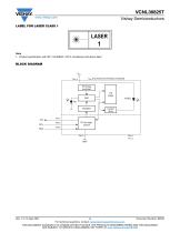
Vishay Semiconductors LABEL FOR LASER CLASS 1 1 Note • Product specification with IEC / EN 60825-1:2014 compliance and above label BLOCK DIAGRAM VDD VDD and anode are internally connected PS timing controller PS buffer DSP Current driver Document Number: 80235 3 For technical questions, contact: [email protected] THIS DOCUMENT IS SUBJECT TO CHANGE WITHOUT NOTICE. THE PRODUCTS DESCRIBED HEREIN AND THIS DOCUMENT ARE SUBJECT TO SPECIFIC DISCLAIMERS, SET FORTH AT www.vishay.com/doc?91000
Open the catalog to page 3
Vishay Semiconductors I2C BUS TIMING CHARACTERISTICS (Tamb = 25 °C, unless otherwise specified) PARAMETER STANDARD MODE Repeated start condition setup time Stop condition setup time Data hold time Data setup time FAST MODE Hold time after (repeated) start condition; after this period, the first clock is generated Clock frequency Bus free time between start and stop condition I2C clock (SCK) high period Clock / data fall time Clock / data rise time Note • Data based on standard I2C protocol requirement, not tested in production t(SUSTA) t(SUSTO) S Start condition Start Stop t(LOSEXT) SCLKACK t(LOWMEXT)...
Open the catalog to page 4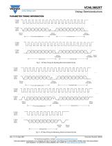
Vishay Semiconductors PARAMETER TIMING INFORMATION I2C BUS CLOCK (SCLK) I C bus slave address byte Command code Data byte high Fig. 2 - I2C Bus Timing for Sending Word Command Format I C bus slave address byte I C bus slave address byte Data byte high Fig. 3 - I2C Bus Timing for Receiving Word Command Format Rev. 1.3, 14-Sep-2021 Document Number: 80235 5 For technical questions, contact: [email protected] THIS DOCUMENT IS SUBJECT TO CHANGE WITHOUT NOTICE. THE PRODUCTS DESCRIBED HEREIN AND THIS DOCUMENT ARE SUBJECT TO SPECIFIC DISCLAIMERS, SET FORTH AT www.vishay.com/doc?91000
Open the catalog to page 5
Vishay Semiconductors TYPICAL PERFORMANCE CHARACTERISTICS (Tamb = 25 °C, unless otherwise specified) Axis Title Relative Response (%) 1st line Ie, rel. - Relative Radiant Intensity Fig. 4 - Normalized Spectral Response Axis Title Axis Title IDD - Supply Current (µA) 1st line IF - Forward Current (mA) 1st line VF - Forward Voltage (V) 2nd line Fig. 5 - Forward Current vs. Forward Voltage Document Number: 80235 6 For technical questions, contact: [email protected] THIS DOCUMENT IS SUBJECT TO CHANGE WITHOUT NOTICE. THE PRODUCTS DESCRIBED HEREIN AND THIS DOCUMENT ARE SUBJECT TO SPECIFIC...
Open the catalog to page 6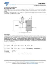
Vishay Semiconductors APPLICATION INFORMATION Pin Connection With the Host VCNL36825T integrates proximity sensor, and IR VCSEL all together with I2C interface. It is very easy for the baseband (CPU) to access PS output data via I2C interface without extra software algorithms. The hardware schematic is shown in the following diagram. One additional 1 μF capacitor in the circuit is used for power supply noise rejection, and 2.2 kΩ is proposed for the pull high resistors of I2C except 10 kΩ applied on INT pin. Vpull_up Fig. 8 - Hardware Pin Connection Diagram Digital Interface VCNL36825T applies...
Open the catalog to page 7
Vishay Semiconductors Function Description VCNL36825T supports different kinds of mechanical designs to achieve the best proximity detection performance for any color of object with more flexibility. The basic PS function settings, such as measurement period, integration time, interrupt, PS start / stop and persistence, are handled by the register PS_CONF2_L. PS_PERIOD controls the PS response time. PS_IT represents the duration of the energy being received. The PS_INT is asserted when the PS detection levels higher than the high threshold level setting (register: PS_THDH) or lower than low threshold...
Open the catalog to page 8All VISHAY catalogs and technical brochures
 VS-E5TH1506THN3
8 Pages
 VS-E5TX1506THN3
8 Pages
 VS-E5TH3006THN3
8 Pages
 VS-E5TX3006THN3
8 Pages
 VS-E5PH3006LHN3
6 Pages
 VS-E5PX3006LHN3
6 Pages
 VS-E5PH6006LHN3
6 Pages
 VS-E5PX6006LHN3
6 Pages
 VS-E5PH7506LHN3
6 Pages
 VS-E5PX7506LHN3
6 Pages
 VS-E5TH1506-M3
7 Pages
 VS-E5TX1506-M3
7 Pages
 VS-E5TH3006-M3
7 Pages
 VS-E5TX3006-M3
7 Pages
 VS-E5PH3006L-N3
8 Pages
 VS-E5PX3006L-N3
7 Pages
 VS-E5PH6006L-N3
7 Pages
 VS-E5PX6006L-N3
7 Pages
 VS-E5PH7506L-N3
7 Pages
 VS-E5PX7506L-N3
7 Pages
 VS-C04ET07T-M3
5 Pages
 VS-C06ET07T-M3
5 Pages
 VS-C08ET07T-M3
5 Pages
 VS-C10ET07T-M3
5 Pages
 VS-C12ET07T-M3
5 Pages
 VS-C16CP07L-M3
5 Pages
 VS-C16ET07T-M3
5 Pages
 VS-C20CP07L-M3
5 Pages
 VS-C20ET07T-M3
5 Pages
 VS-C40CP07L-M3
5 Pages
 P11H
P11H7 Pages
 IHTH-1500MZ-5A
4 Pages
 IHTH-1500TZ-5A
4 Pages
 MFU AT SERIES
8 Pages
 T24
T247 Pages
 CRHA
CRHA4 Pages
 IHXL-1500VZ-5A
5 Pages
 Power Modules
32 Pages
 Bare Die
29 Pages
 TMBS® Rectifiers
2 Pages
 XOSM-531 OSCILLATORS
3 Pages
 IHLP2525EZ-01 INDUCTORS
4 Pages
 HYBRIDS & SUBSTRATES HP - MT
2 Pages
 Fuses HCTF CP Series
5 Pages
 XT49S CRYSTALS
3 Pages
 VOM1271 SOLID-STATE RELAYS
7 Pages
 Si5904DC MOSFETS
9 Pages
 Chip Antenna
6 Pages
 2381 691 90001/HUMIDITY-SENS-E
2 Pages
 Inductors - Power Inductors
2 Pages
 Capacitors - Ceramic
7 Pages
 Capacitors - Radial
5 Pages


Archived catalogs
 RC Thermal Model for 2N7002K
3 Pages
 MLCC Product Road Map
4 Pages


- Connector
- Display module
- Rectangular connector
- Switching relay
- LED display panel
- Position transducer
- Inductive proximity sensor
- Transceiver module
- Electronic display panel
- Linear position transmitter
- Radio antenna
- Analog position transducer
- SMT connector
- Diode
- No-contact position sensor
- Medical equipment display
- Potentiometer
- Ceramic capacitor