
Catalog excerpts
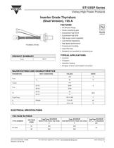
ST103SP Series Vishay High Power Products Inverter Grade Thyristors (Stud Version), 105 A FEATURES • All diffused design • Center amplifying gate • Guaranteed high dV/dt • Guaranteed high dI/dt • High surge current capability • Low thermal impedance • High speed performance TO-209AC (TO-94) • Compression bonding • Lead (Pb)-free • Designed and qualified for industrial level TYPICAL APPLICATIONS PRODUCT SUMMARY IT(AV) • Choppers • Induction heating • All types of force-commutated converters MAJOR RATINGS AND CHARACTERISTICS PARAMETER TEST CONDITIONS ELECTRICAL SPECIFICATIONS VOLTAGE RATINGS VOLTAGE CODE VDRM/VRRM, MAXIMUM REPETITIVE PEAK VOLTAGE V VRSM, MAXIMUM NON-REPETITIVE PEAK VOLTAGE V TYPE NUMBER Document Number: 94365 Revision: 29-Apr-08 IDRM/IRRM MAXIMUM AT TJ = TJ MAXIMUM mA 30 For technical questions, contact: ind-modules@vishay.com
Open the catalog to page 1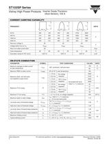
ST103SP Series Vishay High Power Products Inverter Grade Thyristors (Stud Version), 105 A CURRENT CARRYING CAPABILITY ITM Recovery voltage Vr Voltage before turn-on Vd Rise of on-state current dI/dt Case temperature Equivalent values for RC circuit ON-STATE CONDUCTION PARAMETER Maximum average on-state current at case temperature TEST CONDITIONS 180° conduction, half sine wave Maximum peak, one half cycle, non-repetitive surge current Maximum RMS on-state current No voltage reapplied 100 % VRRM reapplied No voltage reapplied 2530 Sinusoidal half wave, initial TJ = TJ maximum Maximum peak...
Open the catalog to page 2
ST103SP Series Inverter Grade Thyristors (Stud Version), 105 A Vishay High Power Products SWITCHING PARAMETER TJ = TJ maximum, VDRM = Rated VDRM, ITM = 2 x dI/dt TJ = 25 °C, VDM = Rated VDRM, ITM = 50 A DC, tp = 1 µs Resistive load, gate pulse: 10 V, 5 Ω source TJ = TJ maximum, ITM = 100 A, commutating dI/dt = 10 A/µs VR = 50 V, tp = 200 µs, dV/dt: See table in device code Typical delay time Maximum turn-off time Maximum non-repetitive rate of rise of turned on current minimum maximum TEST CONDITIONS BLOCKING PARAMETER TEST CONDITIONS Maximum critical rate of rise of off-state voltage TJ =...
Open the catalog to page 3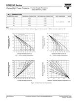
ST103SP Series Vishay High Power Products Inverter Grade Thyristors (Stud Version), 105 A ΔRthJC CONDUCTION CONDUCTION ANGLE SINUSOIDAL CONDUCTION RECTANGULAR CONDUCTION TEST CONDITIONS Note • The table above shows the increment of thermal resistance RthJC when devices operate at different conduction angles than DC Maximum Allowable Case Temperature (°C) Maximum Allowable Case Temperature (°C) Average On-State Current (A) Conduction angle Maximum Average On-state Power Loss (W) Fig. 2 - Current Ratings Characteristics Average On-State Current (A) Fig. 1 - Current Ratings Characteristics...
Open the catalog to page 4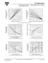
Conduction angle Vishay High Power Products Maximum Average On-State Power Loss (W) Maximum Average On-State Power Loss (W) Inverter Grade Thyristors (Stud Version), 105 A Average On-State Current (A) Maximum Allowable Ambient Temperature (°C) At any rated load condition and with rated VRRM applied following surge Peak Half Sine Wave On-State Current (A) Instantaneous On-State Current (A) Fig. 4 - On-State Power Loss Characteristics Number of Equal Amplitude Half Cycle Current Pulses (N) Fig. 5 - Maximum Non-Repetitive Surge Current Peak Half Sine Wave On-State Current (A) Fig. 7 - On-State...
Open the catalog to page 5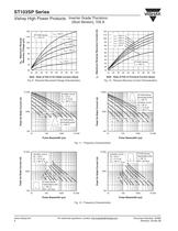
ST103SP Series Vishay High Power Products Inverter Grade Thyristors Qrr - Maximum Reverse Recovery Charge (µC) dI/dt - Rate of Fall of On-State Current (A/µs) Fig. 9 - Reverse Recovered Charge Characteristics Irr - Maximum Reverse Recovery Current (A) dI/dt - Rate of Fall of Forward Current (A/µs) Fig. 10 - Reverse Recovery Current Characteristics 10000 Snubber circuit Rs = 22 Ω Cs = 0.15 µF VD = 80 % VDRM ST103S Series Sinusoidal pulse TC = 60 °C Peak On-State Current (A) Peak On-State Current (A) ST103S Series Sinusoidal pulse TC = 85 °C Snubber circuit Rs = 22 Ω Cs = 0.15 µF VD = 80 %...
Open the catalog to page 6
ST103SP Series Inverter Grade Thyristors (Stud Version), 105 A 10 000 Snubber circuit Rs = 22 Ω Cs = 0.15 µF VD = 80 % VDRM Peak On-State Current (A) Peak On-State Current (A) Vishay High Power Products ST103S Series Trapezoidal pulse TC = 60 °C dI/dt = 100 A/µs ST103S Series Trapezoidal pulse TC = 85 °C dI/dt = 100 A/µs Snubber circuit Rs = 22 Ω Cs = 0.15 µF VD = 80 % VDRM Pulse Basewidth (µs) Fig. 13 - Frequency Characteristics Peak On-State Current (A) Peak On-State Current (A) ST103S Series Sinusoidal pulse ST103S Series Rectangular pulse dI/dt = 50 A/µs Fig. 14 - Maximum On-State...
Open the catalog to page 7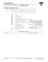
ST103SP Series Vishay High Power Products Inverter Grade Thyristors (Stud Version), 105 A ORDERING INFORMATION TABLE Device code Essential part number S = Compression bonding stud Voltage code x 100 = VRRM (see Voltage ratings table) Reapplied dV/dt code (for tq test conditions) 0 = Eyelet terminals (gate and aux. cathode leads) dV/dt - tq combinations available 1 = Fast-on terminals (gate and aux. cathode leads) 10 dV/dt (V/µs) 20 50 100 200 400 CN DN EN FN* 10 CM DM EM FM HM 12 CL DL EL FL* HL tq (µs) 15 18 CP DP EP FP HP CK DK EK FK HK 20 HJ 25 * Standard part number. All other types...
Open the catalog to page 8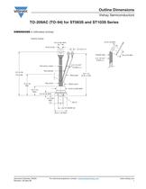
Outline Dimensions Vishay Semiconductors TO-209AC (TO-94) for ST083S and ST103S Series DIMENSIONS in millimeters (inches) Ceramic housing White gate Document Number: 95003 Revision: 30-Sep-08 For technical questions, contact: indmodules@vishay.com
Open the catalog to page 9
Legal Disclaimer Notice www.vishay.com Disclaimer ALL PRODUCT, PRODUCT SPECIFICATIONS AND DATA ARE SUBJECT TO CHANGE WITHOUT NOTICE TO IMPROVE RELIABILITY, FUNCTION OR DESIGN OR OTHERWISE. Vishay Intertechnology, Inc., its affiliates, agents, and employees, and all persons acting on its or their behalf (collectively, “Vishay”), disclaim any and all liability for any errors, inaccuracies or incompleteness contained in any datasheet or in any other disclosure relating to any product. Vishay makes no warranty, representation or guarantee regarding the suitability of the products for any...
Open the catalog to page 10All VISHAY catalogs and technical brochures
-
VS-E5TH1506THN3
8 Pages
-
VS-E5TX1506THN3
8 Pages
-
VS-E5TH3006THN3
8 Pages
-
VS-E5TX3006THN3
8 Pages
-
VS-E5PH3006LHN3
6 Pages
-
VS-E5PX3006LHN3
6 Pages
-
VS-E5PH6006LHN3
6 Pages
-
VS-E5PX6006LHN3
6 Pages
-
VS-E5PH7506LHN3
6 Pages
-
VS-E5PX7506LHN3
6 Pages
-
VCNL36825T
16 Pages
-
VS-E5TH1506-M3
7 Pages
-
VS-E5TX1506-M3
7 Pages
-
VS-E5TH3006-M3
7 Pages
-
VS-E5TX3006-M3
7 Pages
-
VS-E5PH3006L-N3
8 Pages
-
VS-E5PX3006L-N3
7 Pages
-
VS-E5PH6006L-N3
7 Pages
-
VS-E5PX6006L-N3
7 Pages
-
VS-E5PH7506L-N3
7 Pages
-
VS-E5PX7506L-N3
7 Pages
-
VS-C04ET07T-M3
5 Pages
-
VS-C06ET07T-M3
5 Pages
-
VS-C08ET07T-M3
5 Pages
-
VS-C10ET07T-M3
5 Pages
-
VS-C12ET07T-M3
5 Pages
-
VS-C16CP07L-M3
5 Pages
-
VS-C16ET07T-M3
5 Pages
-
VS-C20CP07L-M3
5 Pages
-
VS-C20ET07T-M3
5 Pages
-
VS-C40CP07L-M3
5 Pages
-
P11H
7 Pages
-
IHTH-1500MZ-5A
4 Pages
-
IHTH-1500TZ-5A
4 Pages
-
MFU AT SERIES
8 Pages
-
T24
7 Pages
-
CRHA
4 Pages
-
IHXL-1500VZ-5A
5 Pages
-
Power Modules
32 Pages
-
Bare Die
29 Pages
-
TMBS® Rectifiers
2 Pages
-
XOSM-531 OSCILLATORS
3 Pages
-
IHLP2525EZ-01 INDUCTORS
4 Pages
-
HYBRIDS & SUBSTRATES HP - MT
2 Pages
-
Fuses HCTF CP Series
5 Pages
-
XT49S CRYSTALS
3 Pages
-
VOM1271 SOLID-STATE RELAYS
7 Pages
-
Si5904DC MOSFETS
9 Pages
-
Chip Antenna
6 Pages
-
2381 691 90001/HUMIDITY-SENS-E
2 Pages
-
Inductors - Power Inductors
2 Pages
-
Capacitors - Ceramic
7 Pages
-
Capacitors - Radial
5 Pages
Archived catalogs
-
RC Thermal Model for 2N7002K
3 Pages
-
MLCC Product Road Map
4 Pages


