
Catalog excerpts
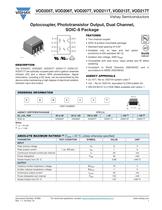
Document Number: 81956 For technical questions, contact: optocoupleranswers@vishay.com www.vishay.com Rev. 1.1, 04-Nov-10 1 Optocoupler, Phototransistor Output, Dual Channel, SOIC-8 Package VOD205T, VOD206T, VOD207T, VOD211T, VOD213T, VOD217T Vishay Semiconductors DESCRIPTION The VOD205T, VOD206T, VOD207T, VOD211T, VOD213T, VOD217T are optically coupled pairs with a gallium arsenide infrared LED and a silicon NPN phototransistor. Signal information, including a DC level, can be transmitted by the device while maintaining a high degree of electrical isolation between input and output. FEATURES • Two channel coupler • SOIC-8 surface mountable package • Standard lead spacing of 0.05" • Available only on tape and reel option (conforms to EIA standard 481-2) • Isolation test voltage, 4000 VRMS • Compatible with dual wave, vapor phase and IR reflow soldering • Compliant to RoHS Directive 2002/95/EC and in accordance to WEEE 2002/96/EC AGENCY APPROVALS • UL1577, file no. E52744 system code Y • cUL - file no. E52744, equivalent to CSA bulletin 5A • DIN EN 60747-5-2 (VDE 0884) available with option 1 Notes (1) IF = 10 mA (2) IF = 1 mA i179018-1 A 1 C 2 A 3 C 4 8 C 7 E 6 C 5 E DVE i179074 ORDERING INFORMATION V O D 2 # # T PART NUMBER AGENCY CERTIFIED/PACKAGE CTR (%) UL, cUL, VDE 40 to 80 63 to 125 100 to 200 > 20 > 100 (1) > 100 (2) SOIC-8 VOD205T VOD206T VOD207T VOD211T VOD213T VOD217T ABSOLUTE MAXIMUM RATINGS (1) (Tamb = 25 °C, unless otherwise specified) PARAMETER TEST CONDITION SYMBOL VALUE UNIT INPUT Peak reverse voltage VR 6 V Peak pulsed current 1 ìs, 300 pps IFM 1 A Continuous forward current per channel IF 30 mA Power dissipation Pdiss 50 mW Derate linearly from 25 °C 0.66 mW/°C OUTPUT Collector emitter breakdown voltage BVCEO 70 V Emitter collector breakdown voltage BVECO 7 V Continuous output current ICmax. 50 mA Power dissipation per channel Pdiss 125 mW Derate linearly from 25 °C 1.67 mW/°C SIOC-8 6.1 mm
Open the catalog to page 1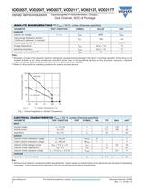
www.vishay.com For technical questions, contact: optocoupleranswers@vishay.com Document Number: 81956 2 Rev. 1.1, 04-Nov-10 VOD205T, VOD206T, VOD207T, VOD211T, VOD213T, VOD217T Vishay Semiconductors Optocoupler, Phototransistor Output, Dual Channel, SOIC-8 Package Notes (1) Stresses in excess of the absolute maximum ratings can cause permanent damage to the device. Functional operation of the device is not implied at these or any other conditions in excess of those given in the operational sections of this document. Exposure to absolute maximum ratings for extended periods of the time can...
Open the catalog to page 2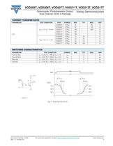
Document Number: 81956 For technical questions, contact: optocoupleranswers@vishay.com www.vishay.com Rev. 1.1, 04-Nov-10 3 VOD205T, VOD206T, VOD207T, VOD211T, VOD213T, VOD217T Optocoupler, Phototransistor Output, Dual Channel, SOIC-8 Package Vishay Semiconductors Fig. 2 - Switching Test Circuit CURRENT TRANSFER RATIO PARAMETER TEST CONDITION PART SYMBOL MIN. TYP. MAX. UNIT IC/IF VCE = 5 V, IF = 10 mA VOD205T CTRDC 40 80 % VOD206T CTRDC 63 125 % VOD207T CTRDC 100 200 % VOD211T CTRDC 20 % VOD213T CTRDC 100 % VCE = 5 V, IF = 1 mA VOD205T CTRDC 13 30 % VOD206T CTRDC 22 45 % VOD207T CTRDC 34 70...
Open the catalog to page 3
www.vishay.com For technical questions, contact: optocoupleranswers@vishay.com Document Number: 81956 4 Rev. 1.1, 04-Nov-10 VOD205T, VOD206T, VOD207T, VOD211T, VOD213T, VOD217T Vishay Semiconductors Optocoupler, Phototransistor Output, Dual Channel, SOIC-8 Package Fig. 3 - Test Circuit for Common Mode Transient Immunity Note • As per IEC 60747-5-5, §7.4.3.8.1, this optocoupler is suitable for “safe electrical insulation” only within the safety ratings. Compliance with the safety ratings shall be ensured by means of protective circuits. COMMON MODE TRANSIENT IMMUNITY PARAMETER TEST CONDITION...
Open the catalog to page 4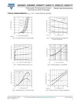
Document Number: 81956 For technical questions, contact: optocoupleranswers@vishay.com www.vishay.com Rev. 1.1, 04-Nov-10 5 VOD205T, VOD206T, VOD207T, VOD211T, VOD213T, VOD217T Optocoupler, Phototransistor Output, Dual Channel, SOIC-8 Package Vishay Semiconductors TYPICAL CHARACTERISTICS (Tamb = 25 °C, unless otherwise specified) Fig. 4 - Forward Current vs. Forward Voltage Fig. 5 - Collector Emitter Current vs. VCE Fig. 6 - Normalized CTRCE vs. Forward Current Fig. 7 - Current Transfer Ratio (normalized) vs. Ambient Temperature Fig. 8 - Switching Speed vs. Load Resistor Fig. 9 - Collector...
Open the catalog to page 5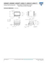
www.vishay.com For technical questions, contact: optocoupleranswers@vishay.com Document Number: 81956 6 Rev. 1.1, 04-Nov-10 VOD205T, VOD206T, VOD207T, VOD211T, VOD213T, VOD217T Vishay Semiconductors Optocoupler, Phototransistor Output, Dual Channel, SOIC-8 Package PACKAGE DIMENSIONS in millimeters 0.91 0.36 4.32 1.14 6.6 R 0.13 1.27 i178020 ISO method A 40° 6.10 1.27 typ. 0.41 0.1 0.2 Lead coplanarity ± 0.001 max. 0.20 7° 3.05 ± 0.05 CL R 0.25 max. 1.02 5° max. Pin one ID 3.91 ± 0.05 5.84 ± 0.05 0.38 ± 0.05 0.51 ± 0.10 2 plcs. 1.49 ± 0.05 3.18 ± 0.05
Open the catalog to page 6
Document Number: 91000 www.vishay.com Revision: 11-Mar-11 1 Disclaimer Legal Disclaimer Notice Vishay ALL PRODUCT, PRODUCT SPECIFICATIONS AND DATA ARE SUBJECT TO CHANGE WITHOUT NOTICE TO IMPROVE RELIABILITY, FUNCTION OR DESIGN OR OTHERWISE. Vishay Intertechnology, Inc., its affiliates, agents, and employees, and all persons acting on its or their behalf (collectively, “Vishay”), disclaim any and all liability for any errors, inaccuracies or incompleteness contained in any datasheet or in any other disclosure relating to any product. Vishay makes no warranty, representation or guarantee...
Open the catalog to page 7All VISHAY catalogs and technical brochures
-
VS-E5TH1506THN3
8 Pages
-
VS-E5TX1506THN3
8 Pages
-
VS-E5TH3006THN3
8 Pages
-
VS-E5TX3006THN3
8 Pages
-
VS-E5PH3006LHN3
6 Pages
-
VS-E5PX3006LHN3
6 Pages
-
VS-E5PH6006LHN3
6 Pages
-
VS-E5PX6006LHN3
6 Pages
-
VS-E5PH7506LHN3
6 Pages
-
VS-E5PX7506LHN3
6 Pages
-
VCNL36825T
16 Pages
-
VS-E5TH1506-M3
7 Pages
-
VS-E5TX1506-M3
7 Pages
-
VS-E5TH3006-M3
7 Pages
-
VS-E5TX3006-M3
7 Pages
-
VS-E5PH3006L-N3
8 Pages
-
VS-E5PX3006L-N3
7 Pages
-
VS-E5PH6006L-N3
7 Pages
-
VS-E5PX6006L-N3
7 Pages
-
VS-E5PH7506L-N3
7 Pages
-
VS-E5PX7506L-N3
7 Pages
-
VS-C04ET07T-M3
5 Pages
-
VS-C06ET07T-M3
5 Pages
-
VS-C08ET07T-M3
5 Pages
-
VS-C10ET07T-M3
5 Pages
-
VS-C12ET07T-M3
5 Pages
-
VS-C16CP07L-M3
5 Pages
-
VS-C16ET07T-M3
5 Pages
-
VS-C20CP07L-M3
5 Pages
-
VS-C20ET07T-M3
5 Pages
-
VS-C40CP07L-M3
5 Pages
-
P11H
7 Pages
-
IHTH-1500MZ-5A
4 Pages
-
IHTH-1500TZ-5A
4 Pages
-
MFU AT SERIES
8 Pages
-
T24
7 Pages
-
CRHA
4 Pages
-
IHXL-1500VZ-5A
5 Pages
-
Power Modules
32 Pages
-
Bare Die
29 Pages
-
TMBS® Rectifiers
2 Pages
-
XOSM-531 OSCILLATORS
3 Pages
-
IHLP2525EZ-01 INDUCTORS
4 Pages
-
HYBRIDS & SUBSTRATES HP - MT
2 Pages
-
Fuses HCTF CP Series
5 Pages
-
XT49S CRYSTALS
3 Pages
-
VOM1271 SOLID-STATE RELAYS
7 Pages
-
Si5904DC MOSFETS
9 Pages
-
Chip Antenna
6 Pages
-
2381 691 90001/HUMIDITY-SENS-E
2 Pages
-
Inductors - Power Inductors
2 Pages
-
Capacitors - Ceramic
7 Pages
-
Capacitors - Radial
5 Pages
Archived catalogs
-
RC Thermal Model for 2N7002K
3 Pages
-
MLCC Product Road Map
4 Pages


