CRHA
1 /4Pages

CRHA
1 /4Pages
Catalog excerpts

CRHA www.vishay.com Vishay Techno Thick Film Chip Resistors, High Voltage FEATURES • AEC-Q200 qualified • High voltage up to 3000 V • Automatic placement capability • Tape and reel packaging available • Termination style: 3-sided wraparound termination • Internationally standardized sizes • Termination material: solder-coated nickel barrier LINKS TO ADDITIONAL RESOURCES • Material categorization: for definitions of compliance please see www.vishay.com/doc?99912 STANDARD ELECTRICAL SPECIFICATIONS GLOBAL MODEL CASE SIZE MAXIMUM WORKING VOLTAGE (1) V TEMPERATURE COEFFICIENT (3) (-55 °C to +155 °C) ± ppm/°C Notes (1) Continuous working voltage shall be P x R or maximum working voltage, whichever is less (2) Resistance values are calibrated at 100 V . Calibration at other voltages available upon request DC (3) Reference only: not for all values specified. Consult factory for your size and value GLOBAL PART NUMBER INFORMATION Global Part Numbering: CRHA1206AF100MFKFB GLOBAL MODEL TERMINAL STYLE TERMINAL MATERIAL RESISTANCE VALUE PACKAGING B = bulk (250 pcs max.) F = T/R (full reel) 1 = T/R (1000 pcs) 5 = T/R (500 pcs) T = T/R (250 pcs min.) Note • For additional information on packaging, refer to the Surface Mount Resistor Packaging document (www.vishay.com/doc?31543) Document Number: 68048 1 For technical questions, contact: [email protected] THIS DOCUMENT IS SUBJECT TO CHANGE WITHOUT NOTICE. THE PRODUCTS DESCRIBED HEREIN AND THIS DOCUMENT ARE SUBJECT TO SPECIFIC DISCLAIMERS, SET FOR
Open the catalog to page 1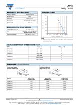
CRHA www.vishay.com Vishay Techno MECHANICAL SPECIFICATIONS Resistive element DERATING CURVE Ruthenium oxide Axis Title 96 % alumina Nickel barrier (standard) Pure tin ENVIRONMENTAL SPECIFICATIONS Operating temperature Solder finish 100 2nd line Rated Power (%) Less than 1.0 % change when tested at full rated power Short time overload Note • Reference only: not for all values specified. Consult factory for your size and value VOLTAGE COEFFICIENT OF RESISTANCE CHART SIZE DIMENSIONS in inches (millimeters) Termination Style A (3-sided wraparound) Termination Style B (top conductor only) Document...
Open the catalog to page 2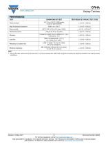
CRHA www.vishay.com Vishay Techno PERFORMANCE TEST Thermal shock TEST RESULTS (TYPICAL TEST LOTS) -55 °C to +150 °C, 1000 cycles, 15 min at each extreme Frequency varied 10 Hz to 2000 Hz in 1 min, 3 directions, 12 h Load life +260 °C solder, 10 s to 12 s dwell, 25 mm/s emergence MIL-STD-202, method 106, 0 % power, 7a and 7b not required High temperature exposure Bias humidity Mechanical shock Resistance to solder heat Moisture resistance Note (1) Due to the high values and small case size, it is recommended the 1206 case size parts be potted for electrical isolation from high humidity conditions...
Open the catalog to page 3
Legal Disclaimer Notice www.vishay.com Disclaimer ALL PRODUCT, PRODUCT SPECIFICATIONS AND DATA ARE SUBJECT TO CHANGE WITHOUT NOTICE TO IMPROVE RELIABILITY, FUNCTION OR DESIGN OR OTHERWISE. Vishay Intertechnology, Inc., its affiliates, agents, and employees, and all persons acting on its or their behalf (collectively, “Vishay”), disclaim any and all liability for any errors, inaccuracies or incompleteness contained in any datasheet or in any other disclosure relating to any product. Vishay makes no warranty, representation or guarantee regarding the suitability of the products for any particular...
Open the catalog to page 4All VISHAY catalogs and technical brochures
 VS-E5TH1506THN3
8 Pages
 VS-E5TX1506THN3
8 Pages
 VS-E5TH3006THN3
8 Pages
 VS-E5TX3006THN3
8 Pages
 VS-E5PH3006LHN3
6 Pages
 VS-E5PX3006LHN3
6 Pages
 VS-E5PH6006LHN3
6 Pages
 VS-E5PX6006LHN3
6 Pages
 VS-E5PH7506LHN3
6 Pages
 VS-E5PX7506LHN3
6 Pages
 VCNL36825T
16 Pages
 VS-E5TH1506-M3
7 Pages
 VS-E5TX1506-M3
7 Pages
 VS-E5TH3006-M3
7 Pages
 VS-E5TX3006-M3
7 Pages
 VS-E5PH3006L-N3
8 Pages
 VS-E5PX3006L-N3
7 Pages
 VS-E5PH6006L-N3
7 Pages
 VS-E5PX6006L-N3
7 Pages
 VS-E5PH7506L-N3
7 Pages
 VS-E5PX7506L-N3
7 Pages
 VS-C04ET07T-M3
5 Pages
 VS-C06ET07T-M3
5 Pages
 VS-C08ET07T-M3
5 Pages
 VS-C10ET07T-M3
5 Pages
 VS-C12ET07T-M3
5 Pages
 VS-C16CP07L-M3
5 Pages
 VS-C16ET07T-M3
5 Pages
 VS-C20CP07L-M3
5 Pages
 VS-C20ET07T-M3
5 Pages
 VS-C40CP07L-M3
5 Pages
 P11H
P11H7 Pages
 IHTH-1500MZ-5A
4 Pages
 IHTH-1500TZ-5A
4 Pages
 MFU AT SERIES
8 Pages
 T24
T247 Pages
 IHXL-1500VZ-5A
5 Pages
 Power Modules
32 Pages
 Bare Die
29 Pages
 TMBS® Rectifiers
2 Pages
 XOSM-531 OSCILLATORS
3 Pages
 IHLP2525EZ-01 INDUCTORS
4 Pages
 HYBRIDS & SUBSTRATES HP - MT
2 Pages
 Fuses HCTF CP Series
5 Pages
 XT49S CRYSTALS
3 Pages
 VOM1271 SOLID-STATE RELAYS
7 Pages
 Si5904DC MOSFETS
9 Pages
 Chip Antenna
6 Pages
 2381 691 90001/HUMIDITY-SENS-E
2 Pages
 Inductors - Power Inductors
2 Pages
 Capacitors - Ceramic
7 Pages
 Capacitors - Radial
5 Pages


Archived catalogs
 RC Thermal Model for 2N7002K
3 Pages
 MLCC Product Road Map
4 Pages


- Connector
- Display module
- Proximity switch
- Rectangular connector
- Switching relay
- Capacitor
- LED display panel
- Position transducer
- Inductive proximity sensor
- Transceiver module
- Electronic display panel
- Linear position transmitter
- Radio antenna
- Analog position transducer
- SMT connector
- Diode
- No-contact position sensor
- Medical equipment display
- Potentiometer
- Ceramic capacitor