9515/9516
1 /4Pages

9515/9516
1 /4Pages
Catalog excerpts

Via Circonvallazione, 10 13018 Valduggia (VC), Italy Tel: +39 0163 47891 Fax: +39 0163 47895 www.vironline.com Fixed orifice DZR brass double regulating valve Threaded F/F (ISO 228/1 for DN15 and DN20, ISO 7/1 Rp above) Olive and nut kit (O/N) for European copper tubing (EN1057) on request: DN15, kit for 15mm pipe DN20, kit for 22mm pipe Design according to BS7350 Tolerance on nominal Kvs ±3% (test according to BS7350) Available in the following versions: Fig. 9515, with test points Fig. 9516, with test points (high pressure TP with drain) STF and TR CU 010 compliant PN25 (Max 25bar up to 110°C, max 20bar above) PN16 with O/N kit (Max 16bar up to 30°C, max 5bar at 120°C) Free of CE marking (cat. according to Art. 4.3 Dir. 2014/68/EU) Working conditions Suitable for: water, -10°C to +130°C (120°C with O/N kit) below 0°C only for water with added antifreeze fluids over 100°C only for water with added anti-boiling fluids Not suitable for: gases group 1 & 2, liquids group 1 (Dir. 2014/68/UE) 15 14 13 N. Part 1 Venturi insert 2 Body 3 Balancing cone 4 Gasket disc 5 Disc1 6 Disc O-ring1 7 Disc stem Stem O-ring 8 9 Union1 10 Stem 11 Bonnet 12 Stop spring ring 13 Screw 14 Handwheel 15 Nut 16 Test point DZR Brass DZR Brass DZR Brass PTFE DZR Brass EPDM Perox DZR Brass EPDM Perox DZR Brass Brass DZR Brass Spring steel Steel ABS (blue) Zinc plated steel DZR Brass2 Test points with EPDM gaskets and polypropylene ties For Fig. 9516, equipped with TP with drain Fig. 9315 160713 Drawings, photos and data contained in this card are provided for information only. VIR reserves the right to change them without
Open the catalog to page 1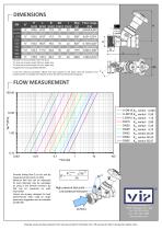
For olive and nut version length 109,2mm, weight +63g For olive and nut version length 119,1mm, weight +65g Suggested flow range applicability (BS7350). If used with measuring manometers different from those proposed by VIR please verify that sensibility of the measuring device is compatible with indicated minimum flow (see flow measurement paragraph) X-DN15, Kvs venturi U-DN15,Kvs venturi L-DN15, Kvs venturi DN15 Kvs venturi DN20 Kvs venturi DN25 Kvs venturi DN32 Kvs venturi DN40 Kvs venturi DN50 Kvs venturi Formula linking flow Q (in l/s) and measured at test points (in kPa). Minimum flow that...
Open the catalog to page 2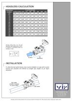
Formula linking flow Q (in l/s) and Kv depends on handwheel position as indicated on table. 2 To obtain the best performances valve must be installed on a pipe with its same nominal size preceded and followed by straight pipe lengths as per figure indications. Min 5xDN (10xDN if installed on pump outlet) Via Circonvallazione, 10 13018 Valduggia (VC), Italy Tel: +39 0163 47891 Fax: +39 0163 47895 www.vironline.com Drawings, photos and data contained in this card are provided for information only. VIR reserves the right to change them without notice.
Open the catalog to page 3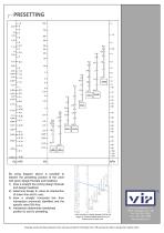
By using diagram above is possible to esteem the presetting position of the valve with given design flowrate and headloss: 1) draw a straight line joining design flowrate and design headloss; 2) determine design Kv value as intersection of drawn line and Kv axis; 3) draw a straight horizontal line from intersection previously identified and the specific valve DN Axis; 4) intersection determines handwheel position to use for presetting. In the example for a design flowrate of 2m3/h and determined for a DN25 valve Via Circonvallazione, 10 13018 Valduggia (VC), Italy Tel: +39 0163 47891 Fax: +39...
Open the catalog to page 4All VIR catalogs and technical brochures
 9900P
9900P4 Pages
 9500/9505/9506
7 Pages
 Catalogue
132 Pages