
- Catalogs
- Vigo Photonics
- VIGO Photonics Products 2024


VIGO Photonics Products 2024

VIGO Photonics Products 2024
This document provides a comprehensive overview of infrared detectors and related products for 2024, offering guidance on selecting the appropriate infrared detector based on wavelength, detectivity, and response speed. It explains the detector code description, detailing aspects such as detector type, optical immersion, cooling stages, wavelength, active area size, package type, window type, and acceptance angle.
The document lists various infrared detectors, including InGaAs, InAs, InAsSb, and HgCdTe detectors, optimized for different spectral ranges and applications. Key features include temperature stability, RoHS compliance, and options for uncooled and TE-cooled detectors. Specific models like PVA-1.7-d1-TO39-wAl2O3-45 are detailed with specifications and applications.
These modules integrate infrared photodetectors and amplifiers, offering advantages such as reduced environmental vulnerability, improved high-frequency performance, and cost-effectiveness. Modules like LabM-I-4 and microM-10.6 are listed with their features and applications.
VIGO offers a range of transimpedance amplifiers categorized by features such as low cut-on frequency, high cut-off frequency, and transimpedance. The document compares different amplifier types, including all-in-one, programmable, standard, small, and fast amplifiers.
This section includes a glossary, usage precautions, and details on optical immersion technology, preamplifiers, thermoelectric cooling, temperature sensor characteristics, and infrared windows and filters. It also describes various detector packages, such as SMD and TO39, with and without immersion or windows.
The document serves as a detailed guide for selecting and understanding infrared detectors and related products, providing essential specifications and application guidance for various industrial and research applications.
Each detector model is described with its spectral range, material compliance, and specific features like optical immersion technology and back-side illumination. The document specifies the cut-on, peak, and cut-off wavelengths, detectivity, current responsivity, time constant, and dynamic resistance for each model under standard conditions.
The detectors are suitable for a wide range of applications including contactless temperature measurement, flame and explosion detection, threat warning systems, gas detection and analysis, breath analysis, combustion process control, and non-destructive material testing. Specific gases detectable include CH4, C2H2, CH2O, HCl, NH3, SO2, C2H6, CO, CO2, NOx, and others.
The document outlines the configuration for each detector, including cooling requirements, temperature sensors, active area dimensions, optical immersion, package type, acceptance angle, and window specifications.
The document lists the maximum ratings for ambient operating temperature, storage temperature, soldering temperature, storage humidity, maximum incident optical power density, maximum bias voltage, and TEC voltage and current. Exceeding these ratings may cause permanent damage to the devices.
Technical drawings for the mechanical layout and pinout of the detectors are referenced, indicating the package type and pin configuration.
Specific amplifier series are recommended for each detector model to optimize performance.
The document includes graphs showing the spectral response, detectivity, and current responsivity across different wavelengths, providing visual insights into the performance characteristics of the detectors.
The document provides detailed specifications and descriptions of various infrared detectors, specifically the PVI-3, PV-4, and PV-5 series. These detectors are used in applications such as gas detection, breath analysis, explosion prevention, emission control, and contactless temperature measurements.
Each detector series is characterized by its spectral range, cooling requirements, temperature sensors, optical immersion, and package type. The document lists specific parameters such as cut-on and cut-off wavelengths, peak wavelength, detectivity, current responsivity, time constant, and dynamic resistance for each detector model.
The document includes technical drawings for various package types such as TO39, TO8, and TO66, detailing the mechanical layout and pin configurations.
Different amplifier series are recommended for each detector model, including SIP, AIP, PIP, MIP, and FIP series, depending on the specific detector and its requirements.
The document outlines the maximum operating conditions for the detectors, including ambient and storage temperatures, soldering temperature, storage humidity, maximum incident optical power density, bias voltage, TEC voltage, and TEC current. Exceeding these ratings may cause permanent damage to the devices.
The detectors are suitable for a wide range of applications, including gas detection and analysis, breath analysis, explosion prevention, emission control, contactless temperature measurements, flame and explosion detection, threat warning systems, and non-destructive material testing.
Key features of the detectors include a wide spectral range, back-side illumination, unique immersion lens technology, and no minimum order quantity requirement. Some detectors are also RoHS-compliant.
The document provides detailed specifications and applications for various series of infrared detectors, focusing on their use in combustion process control and non-destructive material testing. It includes technical specifications, recommended amplifiers, and absolute maximum ratings for different detector models.
The document describes several series of infrared detectors, including PVI-5, PC-5, PCI-5, and PV-6. Each series is characterized by specific features such as spectral range, cooling methods, and package types. The detectors are used in applications like gas detection, temperature measurement, and flame detection.
Detailed specifications are provided for each detector model, including parameters like peak wavelength, detectivity, current responsivity, and time constant. The document also outlines the mechanical layout and pinout for various package types.
The document lists the absolute maximum ratings for parameters such as ambient operating temperature, storage temperature, soldering temperature, and maximum bias voltage. It warns that exceeding these ratings may cause permanent damage to the devices.
The detectors are used in a wide range of applications, including contactless temperature measurement, flame and explosion detection, threat warning systems, and gas leak detection. They are also used in industries like railway transport, industrial monitoring, and dentistry.
The document recommends specific amplifier series for each detector model, ensuring optimal performance and compatibility.
The detectors feature a spectral range from 2.0 to 7.0 µm, back-side illumination, and unique immersion lens technology. They are designed to be RoHS-compliant and do not require a minimum order quantity.
The document provides detailed specifications and descriptions of various infrared (IR) detectors, focusing on their applications, features, and technical specifications. The detectors are primarily used for gas detection, monitoring, and FTIR spectroscopy.
The document describes several series of IR detectors, including PVI-6, PV-8, PVI-8, PVM-8, and PVMI-8. Each series is characterized by specific features such as spectral range, cooling methods, and unique lens technologies.
Each detector series has detailed specifications including cut-on and cut-off wavelengths, peak wavelengths, detectivity, current responsivity, time constant, and dynamic resistance. These parameters are crucial for determining the performance and suitability of the detectors for specific applications.
The document outlines the maximum operating conditions for the detectors, including ambient operating temperature, storage temperature, soldering temperature, storage humidity, maximum incident optical power density, and maximum bias voltage. Exceeding these ratings may lead to permanent damage to the devices.
Technical drawings and pinout configurations for various detector packages such as TO39, TO8, and TO66 are provided, which are essential for integration into systems.
The document lists compatible amplifier types for each detector series, ensuring optimal performance and signal processing.
The detectors are suitable for a range of applications including gas detection and analysis (e.g., CH4, H2S, NO2, SOx), and FTIR spectroscopy, highlighting their versatility in industrial and scientific settings.
Notable features include spectral ranges from 2.0 to 10.0 µm, back-side illumination, and unique immersion lens technology. Some series do not require a minimum order quantity, making them accessible for various scales of operation.
The document provides detailed specifications and applications for various infrared (IR) detectors, focusing on the PVMI, PEM, PVMQ, PC, and PCI series. These detectors are used in applications such as gas detection, CBRN threats detection, CO2 laser measurements, free-space optical communication, FTIR spectroscopy, medical bacteria identification, dentistry, and glucose sensing.
- PVMI Series: Includes models like PVMI-10.6-1×1-TO39-NW-36 and PVMI-2TE-10.6-1×1-TO8-wZnSeAR-36. These detectors have a spectral range of 2.0 to 12.0 µm and are back-side illuminated. They are available in various packages such as TO39, TO8, and TO66, with different cooling options and temperature sensors.
- PEM Series: The PEM-10.6-1×1-PEM-SMA-wZnSeAR-48 model is highlighted, featuring a spectral range of 2.0 to 12.0 µm and a PEM-SMA package. It is designed for applications requiring high sensitivity and specific wavelength detection.
- PVMQ Series: The PVMQ-10.6-1×1-TO8-NW-70 model is a multi-junction quadrant infrared detector with a spectral range of 2.0 to 12.0 µm, suitable for precise spatial resolution applications.
- PC Series: Includes models like PC-4TE-10.6-1×1-TO8-wZnSeAR-70, featuring thermoelectric cooling and a spectral range over 10.3 µm. These detectors are front-side illuminated and offer high detectivity and responsivity.
- PCI Series: The PCI-2TE-10.6-1×1-TO8-wZnSeAR-36 model uses unique immersion lens technology, providing a spectral range up to 12.8 µm. It is designed for enhanced performance in demanding applications.
- Operating Conditions: Ambient operating temperature ranges from -20 to 30°C, with storage temperatures from -20 to 50°C. Soldering temperatures should not exceed 300°C for more than 5 seconds.
- Performance Parameters: Detectors are characterized by parameters such as detectivity (D*), current responsivity (Ri), time constant (τ), and dynamic resistance (Rd). These parameters vary across models and are critical for determining the suitability of a detector for specific applications.
- Absolute Maximum Ratings: Include maximum incident optical power density, bias voltage, and TEC voltage and current. Exceeding these ratings may cause permanent damage to the detectors.
The detectors are used in a wide range of applications, including gas detection (SO2, NH3, SF6), CBRN threats detection, CO2 laser measurements, free-space optical communication, FTIR spectroscopy, medical bacteria identification, dentistry, and glucose sensing.
The document provides technical drawings and pinout configurations for various packages, including TO39, TO8, TO66, and PEM-SMA, ensuring proper integration into systems.
Specific amplifier series are recommended for each detector model to optimize performance, including SIP, AIP, PIP, MIP, and FIP series.
The PCI-10.6 series detectors have specific operational limits to ensure device integrity. The ambient operating temperature ranges from -20 to 30°C, with storage temperatures between -20 to 50°C. Soldering temperatures should not exceed 300°C for more than 5 seconds. The maximum incident optical power density is 2.5 W/cm² for continuous waves or pulses longer than 1 μs, and 10 kW/cm² for shorter pulses. The maximum bias voltage is 1.5 V, with TEC voltage and current limits varying by model.
The document provides technical drawings for various package types, including 2TE-TO8, 2TE-TO66, 4TE-TO8, and 4TE-TO66, detailing the mechanical layout and pin configurations.
The document lists compatible amplifier series for different detector models, such as the AIP, PIP, MIP, and SIP-TO8 series, ensuring optimal performance.
The PCI-12, PCI-13, and PCI-14 series detectors cover a spectral range over 14.0 µm, are back-side illuminated, and utilize unique immersion lens technology. They are suitable for FTIR spectroscopy, gas detection, laser measurements, and more.
Each series, including PCI-3TE-12, PCI-4TE-13, and PCI-4TE-14, is described with details on cooling, temperature sensors, optical area, and package type. Specifications include peak wavelength, detectivity, current responsivity, and time constant, with typical values provided for each parameter.
Graphs illustrate the typical spectral response of the detectors, showing detectivity and current responsivity across different wavelengths.
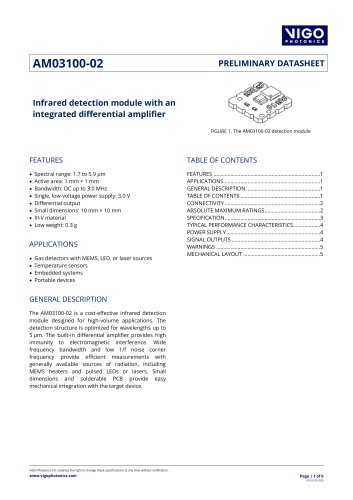
The AMS3140-01 and AMS6140-01 modules feature a spectral range of 2.5 to 5.7 µm or 1.7 to 7 µm, with built-in temperature controllers and low 1/f noise. They are designed for high-volume applications, offering differential output and easy connectivity.
The modules include a 14-pin connector with specific functions for each pin, such as signal output, temperature output, and amplifier supply input. The recommended mating connector is specified for mechanical integration.
The modules have a maximum amplifier and temperature controller supply voltage of 5.5 V, with operational temperatures ranging from -40ºC to 65ºC.
Detailed specifications for the AMS3140-01 and AMS6140-01 modules include spectral characteristics, responsivity, detectivity, and optical parameters, ensuring precise application in various infrared detection scenarios.
The document outlines the specifications for the AMS3140-01 and AMS6140-01 IR detection modules. Key parameters include:
- Output differential offset: -5 to 20 mV
- Output single-ended common mode voltage: 1.22 V (floating), 0.61 V (Rload = 50 Ω)
- Output impedance: 50 Ω
- Output voltage swing: 0.2 V (negative), 2.2 V (positive)
- High cut-off frequency: 4 MHz (AMS3140-01), 2.6 MHz (AMS6140-01)
- Supply current: 50 mA (Vamp and GND), 550 mA (Vcooler and PGND)
- Thermal resistance: 10 K/W
- Thermal power: 1.2 W
- Maximum temperature difference: 60 ºC
- Cooling surface area: 450 mm²
The module requires careful power supply management to avoid interference. It uses two supply paths: Vamp/GND for the amplifier circuit and Vcooler/PGND for the thermoelectric cooler (TEC). Decoupling capacitors are recommended for both paths.
The module includes a built-in TEC for temperature control, which can be adjusted using a resistor, external voltage source, or DAC output. Methods to reduce interference include using separate power supplies, common mode filters, and small resistors. The module's responsivity is stable only when the chip temperature is constant.
The thermal design involves managing heat from the TEC and electronic components. A heatsink is necessary, and its size depends on the application. The document provides formulas for calculating thermal resistance and examples of thermal management strategies.
Output signals should be short and close to each other to minimize EMI interference. The outputs have a fixed impedance of 50 Ω, and termination is recommended for fast pulsed sources. The document also discusses methods to adjust the DC output offset.
The document provides technical specifications and guidelines for IR detection modules, specifically the AMS3140-01, AMS6140-01, LabM-I-4, LabM-I-5, and LabM-I-6-01 models. These modules are based on HgCdTe TE cooled optically immersed photovoltaic detectors and are used in various applications such as gas detection, temperature measurement, and emission control.
The modules cover a spectral range from 2.3 to 7.0 µm with frequency bandwidths ranging from DC to 18 MHz. They feature high performance, reliability, DC offset compensation, and built-in fans. The modules are compatible with optical accessories and offer versatility and flexibility.
Thin-film resistors are recommended to avoid flicker noise. For high impedance loads, specific formulas are provided to calculate the impact of resistors on outputs. The modules require a heatsink for optimal operation, and precise resistors with a tolerance of 0.1% are advised to maintain signal path symmetry. Mechanical stress should be minimized by using all mounting holes and thermal grease if necessary.
The modules are suitable for gas detection, breath analysis, explosion prevention, emission control, and contactless temperature measurements. They are also used in research, prototyping, and various industrial applications.
The modules allow for programmable gain, bandwidth, coupling (AC/DC), detector temperature, and output voltage offset. They include accessories such as SMA-BNC and LEMO-DB9 cables, and require a PTCC-01 series TEC controller.
The modules have specific operating and storage temperature ranges, humidity conditions, and maximum incident optical power densities. Exceeding these ratings may cause permanent damage to the device.
The document provides comprehensive technical details and guidelines for the use and application of IR detection modules, emphasizing the importance of precise component selection and mechanical stability for optimal performance.
The document provides detailed specifications and features of various infrared (IR) detection modules designed for a range of applications including gas detection, spectroscopy, and optical communication. These modules are based on HgCdTe (Mercury Cadmium Telluride) photovoltaic detectors and are equipped with features like TE cooling, transimpedance amplifiers, and integrated TEC controllers.
- Spectral Range: 2.0 to 13.0 µm across different models.
- Frequency Bandwidth: Ranges from DC to 1.25 GHz depending on the module.
- Detectivity (D*): Varies with wavelength and frequency, with values provided for specific conditions.
- Voltage Responsivity (Rv): Detailed for peak and specific wavelengths.
- Output Noise Voltage Density: Specified for different frequencies.
- Power Supply: Typically requires ±9 V or 5 V, with current consumption details provided.
- Weight: Varies from 40 g to 235 g depending on the module.
- High performance and reliability with built-in fans and DC offset compensation.
- Compatibility with optical accessories and versatile mounting options.
- Programmable parameters including gain, bandwidth, and detector temperature.
- Gas detection and analysis (e.g., SO2, NH3, SF6).
- CO2 laser measurements and free-space optical communication.
- Medical applications like bacteria identification and glucose sensing.
- Research and prototyping in spectroscopy and LIDAR systems.
The document outlines the maximum operating conditions for temperature, humidity, and optical power density to prevent device damage.
Each module comes with specific cables and adapters, with additional accessories available for enhanced functionality.
The document provides detailed specifications and features of various infrared (IR) detection modules and accessories, focusing on the UHSM-I-10.6 and SM-I-12 models. These modules are designed for high-performance IR detection applications, utilizing HgCdTe (Mercury Cadmium Telluride) technology with thermoelectric cooling.
- UHSM-I-10.6: This module operates within a spectral range of 3.0 to 12.0 µm, with a frequency bandwidth of 300 Hz to 900 MHz. It features a peak wavelength of 8.0 µm and a specific wavelength of 10.6 µm. The detectivity at peak wavelength is 6.7×109 cm·Hz1/2/W, and the voltage responsivity is 2.7×10³ V/W.
- SM-I-12: This module covers a spectral range up to 14.0 µm, with a frequency bandwidth from 10 Hz to 1 MHz. It has a peak wavelength of 10.0 µm and a specific wavelength of 12.0 µm. The detectivity at peak wavelength is 3.4×109 cm·Hz1/2/W, and the voltage responsivity is 1.5×10⁵ V/W.
- Both modules are compatible with optical accessories and feature integrated thermoelectric cooling (TEC) systems for enhanced performance and reliability.
- The UHSM-I-10.6 includes a DC monitor and operates with a single power supply, while the SM-I-12 requires an external TEC controller and heatsink.
- These modules are suitable for various applications, including dual-comb spectroscopy, LIDARs, free-space optical communication, and gas detection.
- Both modules have an ambient operating temperature range of 10 to 30 °C and a storage temperature range of -20 to 50 °C. They can handle humidity levels from 10 to 90% without dew condensation.
- The document also describes accessories like transimpedance amplifiers (AIP, PIP, MIP series) that are compatible with these IR detectors, offering features like adjustable gain, AC/DC coupling, and integrated cooling systems.
The document provides detailed specifications and features of various transimpedance amplifiers and accessories in the MIP, SIP-TO8, SIP-TO39, and FIP series, as well as the PTCC-01 and PPS-03 series power supplies. These products are designed for use with VIGO IR detectors and include features such as adjustable gain, compatibility with optical accessories, and requirements for external components like TEC controllers and heatsinks.
- MIP Series: Offers a frequency bandwidth up to 250 MHz, with fixed transimpedance up to 200 kV/A. The output voltage swing varies based on load and frequency, and the power supply requirements differ for frequencies above and below 1 MHz.
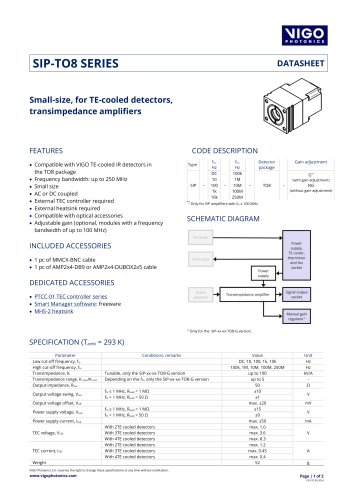
- SIP-TO8 and SIP-TO39 Series: Both series provide tunable transimpedance up to 100 kV/A for specific versions, with a frequency bandwidth up to 250 MHz. They require external TEC controllers and heatsinks for optimal performance.
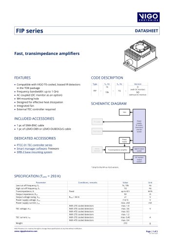
- FIP Series: Designed for fast applications with a frequency bandwidth up to 1 GHz, featuring fixed transimpedance up to 8.5 kV/A and integrated fan for heat dissipation.
- PTCC-01 Series: Programmable TEC controllers with options for advanced, basic, and OEM configurations, offering precise temperature control and compatibility with various VIGO IR detection modules.
- PPS-03 Series: Preamplifier power supplies providing output voltages of ±9 VDC or ±15 VDC, suitable for uncooled detectors in the TO39 package.
Detailed mechanical layouts and pinout configurations are provided for each series, ensuring proper integration with other components and systems.
Each product series includes specific ambient operating and storage temperature ranges, as well as humidity conditions, to prevent damage and ensure reliability.
Each series comes with specific cables and accessories, such as MMCX-BNC and AMP2×4-DB9 cables, and may require additional components like TEC controllers and heatsinks for full functionality.
The document provides detailed specifications and descriptions of various accessories and components related to VIGO detection modules and AMS module series. It includes information on cable types, mounting systems, heatsinks, module holders, optical adapters, amplifiers, low-pass filters, flexible stack extenders, electrical adapters, and digital processing add-ons.
The document lists several cable types with specifications such as USB TypeA-MicroB, KK2-POWER, JWPF-DB9, LEMO-DB9, AMP2x4-DB9, AMP2×4-DUBOX2×5, LEMO-DUBOX2×5, SMA-BNC, SMA-SMA, MMCX-BNC, and MMCX-SMA, with varying lengths and purposes.
The DRB-2 system is designed for VIGO detection modules, featuring adjustable height and compatibility with M6 optical breadboards. It includes a base plate, mounting post, and post holder, each with specific materials and weights.
The MHS-2 heatsink is dedicated to VIGO detection modules with TE-cooled detectors, offering a thermal resistance of ~1.5 K/W and made of black anodized aluminum.
The MH-1 is designed for the assembly of VIGO detection modules and is compatible with the DRB-2 mounting system.
The OTA allows for the integration of VIGO detection modules with optical components, compatible with Thorlabs SM1 threaded lens tubes.
The AMS-x10-AMP and AMS-x10-ACAMP are external amplifiers for the AMS module series, providing differential gain and designed for rapid prototyping. They include detailed electrical diagrams and connectivity information.
The AMS-100k-LPF is an external low-pass filter for the AMS module series, designed for rapid prototyping and proof-of-concept work, with a bandwidth of 100 kHz.
The AMS-90-FLEX is a semi-flex board for the AMS modules, allowing flexible connections between modules and other PCBs.
The AMS-1.27-EA is an accessory for the AMS module series, featuring a standard 1.27 mm socket for rapid prototyping.
The AMS-HS is a heatsink for the AMS detection module series, designed for easy integration with external optics and featuring a thermal resistance of 6 K/W.
The AMS-DIG-PROC is a digital accessory for the AMS detection module series, offering onboard acquisition and processing, with multiple processing algorithms and communication interfaces.
The document provides technical specifications and operational guidelines for the AMS-DIG-PROC, a device used in embedded systems for temperature and gas sensing. It includes details on connectivity, electrical diagrams, absolute maximum ratings, processing pipeline, communication protocols, configuration, work modes, and processing algorithms.
The AMS-DIG-PROC operates with a 3.3V supply and supports a temperature range from -40ºC to 65ºC. It features a sampling rate of 7 MHz and a 16-bit ADC resolution. The device is designed for rapid prototyping with embedded systems.
The device includes two sockets, P1 and P2, with specific pin functions. P2 is rotated to prevent incorrect connections. The schematic diagram outlines the connections and components, including the AMS module socket and output socket.
The document specifies voltage limits for various inputs and outputs, including Vamp, Vcooler, and UART_RX/TX. Exceeding these limits may cause permanent damage.
The AMS-DIG-PROC features a configurable processing pipeline with four slots, each capable of handling 2048 16-bit samples. Processing can be disabled for faster data rates, but this may lead to data loss.
The device uses a 3.3V UART interface with a default speed of 1 Mbit/s. It employs Consistent Overhead Byte Stuffing (COBS) for packet framing and CRC32/POSIX checksum for data integrity.
Configuration parameters can be saved to nonvolatile memory. The device supports various work modes, including STOP, FREE RUNNING, TRIGGER INPUT, TRIGGER OUTPUT, and SIMULATION, each with specific operational characteristics.
Each work mode is designed for specific use cases, such as continuous data acquisition or synchronized sampling with external signals. The document provides detailed instructions for configuring and reading work mode settings.
The AMS-DIG-PROC allows for configurable processing algorithms assigned to each processing slot. The default setting is 'No processing,' where data passes through unmodified.
The document provides technical specifications and operational procedures for the AMS-DIG-PROC and AMS-DIG-USB products, focusing on data processing methods, mechanical requirements, and connectivity features.
The document outlines various data processing techniques for the AMS-DIG-PROC, including simple averaging, sample-wise and buffer-wise IIR filtering, oversampling, peak-peak measurement, and buffer-wise decimation. Each method is described with its message ID, slot ID, and specific parameters such as weight or ratio, emphasizing the importance of configuration for optimal performance.
The AMS-DIG-PROC and AMS-DIG-USB require careful mechanical assembly to avoid damage. The document specifies the use of spacers and the need for secure attachment using screws and nuts to prevent mechanical stress on sensitive components.
The AMS-DIG-USB serves as a USB adapter for the AMS-DIG-PROC, facilitating communication and power supply through a single USB connection. It supports up to 1 Mbit/s transfer rate and includes a virtual COM port for easy integration with PC-based measurement software. The SMA connector allows for trigger input and output, enabling synchronization with external signals.
The products are suitable for rapid prototyping, PC-based measurements, and use with temperature and gas sensors in embedded systems.
The document provides detailed specifications for both products, including electrical parameters, mechanical dimensions, and absolute maximum ratings. It emphasizes the importance of adhering to these specifications to prevent device damage.
A glossary section explains key terms related to infrared detectors, including photoconductive and photovoltaic detectors, active element materials, and various wavelength and detectivity parameters.
Current responsivity is the ratio of photocurrent to the power of radiation, typically measured for monochromatic and blackbody radiation. It remains constant for weak radiation but decreases with stronger radiation.
Describes the detector's time response, related to the 3dB high cut-off frequency. It is the time taken to reach approximately 37% of the initial signal value.
Frequency-dependent noise occurring in biased devices, with a corner frequency where low-frequency noise equals white noise.
The temperature of the detector's active element.
The maximum cone angle for capturing incoming radiation, identical to the Field of View (FOV) in systems without external objectives.
These integrate a detector, preamplifier, thermoelectric cooler, and other components. They are characterized by their spectral and frequency responsivity and detectivity.
The output voltage divided by the optical power incident on the detector.
The frequency at which output voltage noise density is measured.
The current to voltage conversion ratio.
Noise voltage density measured at the preamplifier output.
Include parameters like maximum current, voltage, heat pumping capacity, and temperature stability. They are crucial for maintaining detector performance.
Detectors should operate within specified temperature and voltage limits to avoid damage. Proper storage and handling are essential to maintain performance.
Enhances performance by integrating a microlens with the detector, increasing detectivity and reducing capacitance.
Used to amplify weak signals and protect detectors. Transimpedance preamplifiers are preferred for their linearity and frequency response.
Thermoelectric coolers (TECs) are used in detectors to manage temperature, shifting the cut-off wavelength in HgCdTe detectors towards longer wavelengths and in InAs and InAsSb detectors towards shorter wavelengths. TECs operate based on the Peltier effect and require a DC power supply. Proper heat sinking is crucial to dissipate heat generated by the TEC or excessive optical irradiation. A heat-conductive epoxy or silicon grease is recommended to enhance thermal contact between the detector header and the heat sink. The recommended thermal resistance for heat sinks varies with the TEC stage: ~2 K/W for 1TE, 2TE, and 3TE coolers, and ~1 K/W for 4TE coolers.
The document provides detailed parameters for TECs across different stages (1TE to 4TE), including active element temperature, maximum TEC voltage, and current. For instance, the active element temperature ranges from ~253 K for 1TE to ~197 K for 4TE.
Detectors with thermoelectric cooling are equipped with a built-in thermistor for precise temperature control. The thermistor's resistance varies with temperature, and the document provides a detailed table of resistance values at different temperatures.
VIGO offers standard infrared windows such as 3-degree wedged sapphire, zinc selenide with anti-reflection coating, and planar silicon with anti-reflection coating. These windows prevent interference effects. Infrared filters are available to transmit specific wavelength bands, aiding in focusing on particular spectral regions. The document lists various bandpass filters with their center wavelengths and hardness.
Uncooled detectors are available in TO39 and SMD packages, while thermoelectrically cooled detectors are mounted in metal packages like TO39, TO8, and TO66, sealed with infrared windows. These packages are filled with noble gases to prevent condensation and include humidity absorbers and anti-convection shields for stability.
Catalog excerpts

MIGO PHOTONICS
Open the catalog to page 1
How to choose an infrared detector? 5 Detector code description 6 Selected Line products 7
Open the catalog to page 2
Optical immersion technology 188 Preamplifiers for infrared detectors 189 Thermoelectric cooling, heat sinking 191 Temperature sensor characteristics 192 Infrared windows and filters 193 TO39 package (3 pins) - no immersion, PEM-SMA package
Open the catalog to page 3
\IIGO PRODUCTS | 2024 | INTRODUCTION \IIGO PRODUCTS | 2024 | INTRODUCTION How to choose an infrared detector?For making a detector selection, the following points should be taken into consideration: • wavelength or wavelength range, VIGO detectors are optimized for various wavelengths. Depending on the required parameters a proper detector type should be selected. Detector series Spectral response range (pm)
Open the catalog to page 5
Detector code description Different information such as detector type, optical immersion, number of stages thermoelectric cooler, the specific wavelength, size of active (or optical) area, package type, window type and acceptance angle combine a detector code. Specific Active/optical Acceptance Detector type Immersion - Cooling - - r - Package - Window - wavelength area angle How to choose an amplifier? The infrared detection module integrates infrared photodetector and amplifier in a common package. The integration makes detectors less vulnerable to: • electrostatic discharges, • electromagnetic...
Open the catalog to page 6
NIGO PRODUCTS | 2024 | INTRODUCTION NIGO PRODUCTS | 2024 | INTRODUCTION Selected Line products VIGO Selected Line products are the most popular infrared detectors and detection modules. These devices are suitable for both laboratory research as well as testing, prototyping, and R&D stages, and in a variety of MWIR and LWIR industrial applications. • Detection modules dedicated to specific • Very good repeatability in mass production applications • Cost-effective solutions • High performance and reliability • Fast delivery
Open the catalog to page 7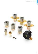
\IIGO PRODUCTS | 2024 | IR DETECTORS
Open the catalog to page 9
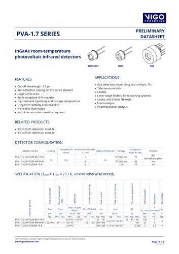
PVA-1.7-d1-TO39-wAl2O3-45InGaAs room-temperature photovoltaic infrared detector FEATURES • Cut-off wavelength: 1.7 |jm • RoHS-compliant III-V material • High ambient operating and storage temperature • Long-term stability and reliability • Front-side illuminated • No minimum order quantity required • Gas detection, monitoring and analysis: CH4 • Laser range finder, laser warning system • Lasers and diodes life tests • Food analysis • Pharmaceutical analysis
Open the catalog to page 10
SPECTRAL RESPONSE (Typ., Tamb = 293 K) Ct-Vb CHARACTERISTICS (Typ., Tamb = 293 K) 200 Terminal capacitance, Ct (pF) Jdark-Vb CHARACTERISTICS (Typ., Tamb = 293 K) Dark current density, Jd (A/cm2) MECHANICAL LAYOUT AND PINOUT TO39 (3 pins) package (with window) – Technical drawing (p. 199) ABSOLUTE MAXIMUM RATINGS Parameter Test conditions/remarks Ambient operating temperature, Tamb Detector parameters depend on Tamb Storage temperature, Tstg Soldering temperature Storage humidity Maximum bias voltage, Vb max Stresses beyond those listed under absolute maximum ratings may cause permanent damage...
Open the catalog to page 11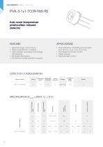
PVA-3-1x1-TO39-NW-90InAs room temperature photovoltaic infrared detectorFEATURES • Spectral range: 2.3 to 3.5 pm • RoHS-compliant III-V material • High ambient operating and storage temperature • Back-side illuminated • No minimum order quantity required • Gas detection, monitoring and analysis: H2O, HF, ch4, c2h2, c2h4, c2h6, nh3 • Combustion process control • Green energy • Medical laser control
Open the catalog to page 12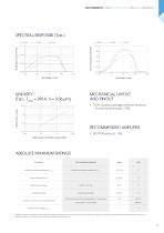
MECHANICAL LAYOUT AND PINOUT TO39 (3 pins) package (without window) – Technical drawing (p. 198) Optical power of incident radiation (mW) ABSOLUTE MAXIMUM RATINGS Parameter Test conditions/remarks Ambient operating temperature, Tamb Detector parameters depend on Tamb Storage temperature, Tstg Soldering temperature Storage humidity Continuous wave (CW) or single pulses >1 μs duration Single pulses <1 μs duration Maximum incident optical power density Maximum bias voltage, Vb max Stresses beyond those listed under absolute maximum ratings may cause permanent damage to the device. Constant or repeated...
Open the catalog to page 13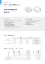
PVA-3-d1.2-SMD series InAs room temperature photovoltaic infrared detectorsFEATURES • Spectral range: 1.3 to 3.6 pm (without filter) • Front-side illuminated • III-V material compliant with the RoHS Directive • High ambient operating and storage temperature • Compact, surface mount type ceramic package (size 4x4 mm2) • Compatible with lead-free solder reflow • No minimum order quantity required • Gas detection, monitoring and analysis: H2O, HF, ch4, c2h2, c2h4, c2h6, nh3 • Combustion process control • Green energy • Medical laser control SPECIFICATION (Tamb = 293 K, Vb = 0 V) Detector symbol
Open the catalog to page 14
PRODUCTS | 2024 | IR DETECTORS | PVA-3-d1.2-SMD series SPECTRAL RESPONSE (Typ., Tamb = 293 K) PVA-3-d1.2-SMD-NW-115, PVA-3-d1.2-SMD-pAl2O3-115 RECOMMENDED REFLOW SOLDERING CONDITIONS MECHANICAL LAYOUT AND SIGNAL OUTPUT PEAK TEMPERATURE 230-240°C max. COOLING 20 s max. 6°C/s max. Temperature SMD package (without window) – Technical drawing (p. 195) SMD package (with window) – Technical drawing (p. 196) 25°C TO PEAK TEMPERATURE 360 s max. Time Desoldering and re-soldering the component may cause degradation of the detector. ABSOLUTE MAXIMUM RATINGS Parameter Test conditions/remarks Ambient operating...
Open the catalog to page 15
NIGO PRODUCTS | 2024 | IR DETECTORS PVIA-5-1x1-TO39-NW-36InAsSb room temperature optically immersed photovoltaic infrared detector FEATURES • Spectral range: 2.6 to 5.3 pm • RoHS-compliant III-V material • High ambient operating and storage temperature • Unique optical immersion technology applied • Back-side illuminated • No minimum order quantity required • Contactless temperature measurement: railway transport, industrial and laboratory processes monitoring • Flame and explosion detection • Threat warning systems • Heat-seeking, thermal signature detection • Gas detection, monitoring and analysis:...
Open the catalog to page 16All Vigo Photonics catalogs and technical brochures
 4EM-5
4EM-52 Pages
 microM-10.6
3 Pages
 LabM-I-4
3 Pages
 AM03100-02
6 Pages
 IC01410-01, IC01420-01
2 Pages
 FIP series
2 Pages
 SIP-TO8 SERIES
2 Pages
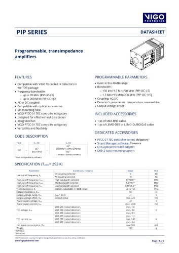 PIP SERIES
2 Pages
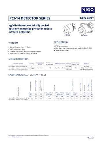 PCI-14 DETECTOR SERIES
2 Pages
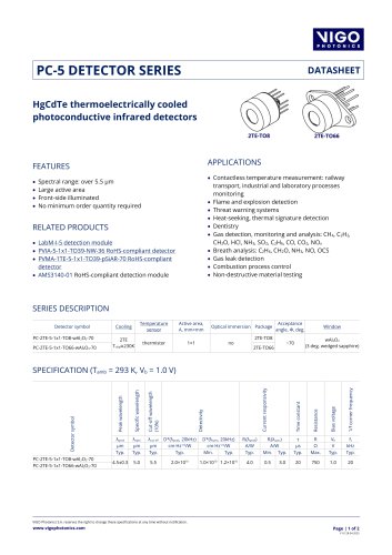 PC-5 DETECTOR SERIES
2 Pages
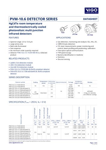 PVM-10.6 DETECTOR SERIES
2 Pages
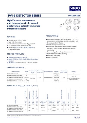 PVI-6 DETECTOR SERIES
2 Pages
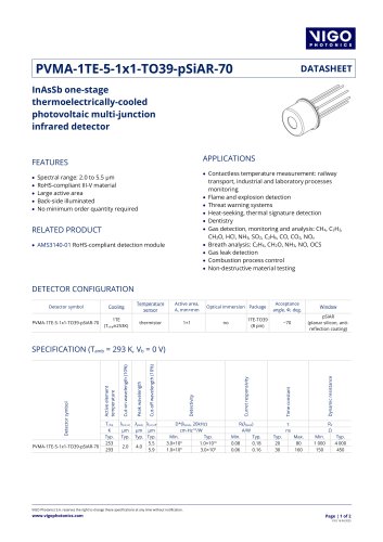 PVMA-1TE-5-1x1-TO39-pSiAR-70
2 Pages
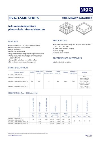 PVA-3-SMD SERIES
2 Pages
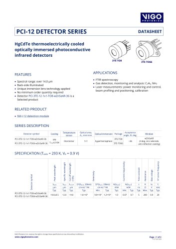 PCI-12 DETECTOR SERIES
2 Pages
 PVA-1.7 SERIES
2 Pages
 PC-LN2-19-1x1-VFP-NW-50
2 Pages
- AC/DC power supply
- Signal amplifying integrated circuit
- Electronic filter
- Low-pass electronic filter
- DC amplifier
- Single-channel amplifier
- Active electronic filter
- Compact amplifier
- Aluminum heat sink
- Adjustable amplifier
- Programmable amplifier
- Differential amplifier
- Infrared image sensor
- Infrared detector power supply
- AC amplifier