

DCM2322x50T1360y6z
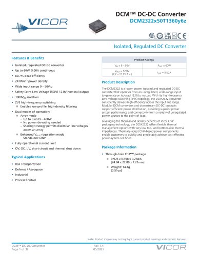
DCM2322x50T1360y6z
- Isolated, regulated DC-DC conversion with up to 60W output and 5.00A continuous current.
- Peak efficiency of 89.7% and power density of 241W/in3.
- Wide input voltage range from 9 to 50VDC.
- 3000VDC isolation and Safety Extra Low Voltage (SELV) output.
- Zero-voltage switching (ZVS) for efficient high-frequency operation.
- Dual operation modes: Array mode (up to 8 units, 480W) and Enhanced VOUT regulation mode (standalone 60W).
- Comprehensive protection features including overvoltage, overcurrent, undervoltage, short circuit, and thermal shutdown.
- Input Voltage: 9 – 50V
- Output Voltage: 12.0V (trim range 7.2 – 13.2V)
- Output Current: 5.00A
Catalog excerpts
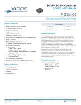
VICOR DCM™ DC-DC Converter DCM2322x50T1360y6z Isolated, Regulated DC Converter Product Ratings The DCM2322 is a lower-power, isolated and regulated DC-DC converter that operates from an unregulated, wide-range input to generate an isolated 12.0VDC output. With its high-frequency zero-voltage switching (ZVS) topology, the DCM2322 converter consistently delivers high efficiency across the input line range. Modular DCM converters and downstream DC-DC products support efficient power distribution, providing superior power system performance and connectivity from a variety of unregulated power sources to the point-of-load. Features & Benefits • Isolated, regulated DC-DC converter • Wide input range 9 - 50VDC • Safety Extra Low Voltage (SELV) 12.0V nominal output ■ Enables low-profile, high-density filtering • Dual modes of operation: - No power de-rating needed - Sharing strategy permits dissimilar line voltages across an array ■ Enhanced VOUt regulation mode • Fully operational current limit • OV, OC, UV, short circuit and thermal shut down Typical Applications • Rail Transportation • Defense / Aerospace • Process Control Product Description Leveraging the thermal and density benefits of Vicor ChiP packaging technology, the DCM2322 offers flexible thermal management options with very low top- and bottom-side thermal impedances. Thermally-adept ChiP-based power components enable customers to quickly and predictably achieve cost-effective power-system solutions. Package Information • Through-hole ChiP™ package Note: Product images may not highlight current product markings and cosmetic features. DCM™ DC-DC Converter Page 1 of 32
Open the catalog to page 1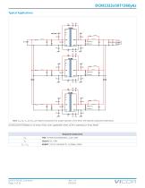
Note: CIN, Rb, Cb1 and Cb2 are required components for proper operation of the DCM. See required components table below. DCM2322x50T1360y6z in an array of four units; applicable when DCM is operating in Array Mode DCM™ DC-DC Converter Page 2 of 32
Open the catalog to page 2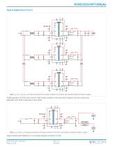
DCM2322x50T1360y6z Typical Applications (Cont.) Note: CIN, Rb, Cb1 and Cb2 are required components for proper operation of the DCM. See required components table on page 2. Parallel operation of DCMs with common-mode chokes installed on the input side to suppress common-mode noise; applicable when DCM is operating in Array Mode Non-isolated Point-of-Load Regulator Note: CIN, Rb and Cb are required components for proper operation of the DCM. See required components table on page 2 Single DCM2322x50T1360y6z to a non-isolated regulator and direct-to-load DCM™ DC-DC Converter Page 3 of 32
Open the catalog to page 3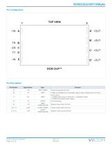
DCM™ DC-DC Converter Page 4 of 32 Rev 1.4 05/2025 VICCDR
Open the catalog to page 4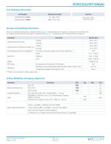
Part Ordering Information
Open the catalog to page 5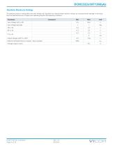
The absolute maximum ratings below are stress ratings only. Operation at or beyond these maximum ratings can cause permanent damage to the device. Electrical specifications do not apply when operating beyond rated operating conditions.
Open the catalog to page 6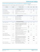
Specifications apply over all line, trim and load conditions, internal temperature T|NT = 25°C, unless otherwise noted. Boldface specifications apply over the temperature range of -40°C < TINT < 125°C for T-Grade and -55°C < TINT < 125°C for M-Grade.
Open the catalog to page 7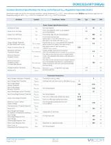
Specifications apply over all line, trim and load conditions, internal temperature T|NT = 25°C, unless otherwise noted. Boldface specifications apply over the temperature range of -40°C < TINT < 125°C for T-Grade and -55°C < TINT < 125°C for M-Grade.
Open the catalog to page 8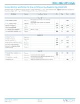
Specifications apply over all line, trim and load conditions, internal temperature T|NT = 25°C, unless otherwise noted. Boldface specifications apply over the temperature range of -40°C < TINT < 125°C for T-Grade and -55°C < TINT < 125°C for M-Grade.
Open the catalog to page 9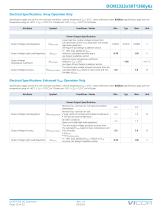
Specifications apply over all line, trim and load conditions, internal temperature T|NT = 25°C, unless otherwise noted. Boldface specifications apply over the temperature range of -40°C < TINT < 125°C for T-Grade and -55°C < TINT < 125°C for M-Grade.
Open the catalog to page 10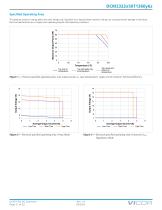
DCM2322x50T1360y6z Specified Operating Area Maximum Output Power (W) The absolute maximum ratings below are stress ratings only. Operation at or beyond these maximum ratings can cause permanent damage to the device. Electrical specifications do not apply when operating beyond rated operating conditions. 100 Top, leads and bottom at temperature Top and leads only at temperature Figure 1 — Thermal specified operating area: max output power vs. case temperature, single unit at minimum full-load efficiency Average Output Current (A) DCM™ DC-DC Converter Page 11 of 32 High Trim Figure 2 — Electrical...
Open the catalog to page 11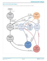
DCM2322x50T1360y6z High-Level Functional State Diagram Conditions that cause state transitions are shown along arrows. Sub-sequence activities listed inside the state bubbles. EN = False tMIN-OFF delay NON LATCHED FAULT tOFF Powertrain: Stopped FT = True tINIT delay Powertrain: Stopped FT = True EN = False tOFF-MIN delay STANDBY Powertrain: Stopped FT = True EN = True and No Faults tON delay EN = False tOFF delay SOFT START VOUT Ramp Up tss delay Powertrain: Active FT = Unknown r Oo VL O O VL ut Inp put U n I REGULATION MODE SELECTION Only applies after initialization sequence Fault Removed Powertrain:...
Open the catalog to page 12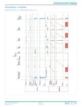
DCM™ DC-DC Converter Page 13 of 32 FULL LOAD VOUT-NOM FULL LOAD 1 Input Power On - Trim Inactive 4 EN Latched 2 3 5 Ramp to TR EN Full Load Ignored Low 9 Input returned to zero Timing Diagrams – Array Mode Module inputs are shown in blue; module outputs are shown in brown
Open the catalog to page 13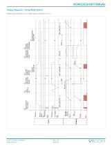
DCM™ DC-DC Converter Page 14 of 32 FULL LOAD FULL LOAD 10 Input Power On - Trim Active 12 Load dump and reverse current 13 Vout OVP (primary sensed) 14 Latched fault cleared 15 Current Limit with Resistive Load 16 Resistive Load with decresing R 17 Overload induced Output UVP Timing Diagrams – Array Mode (Cont.) Module inputs are shown in blue; module outputs are shown in brown
Open the catalog to page 14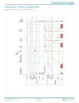
DCM™ DC-DC Converter Page 15 of 32 FULL LOAD FULL LOAD 1 Input Power On - Trim Inactive 2 3 Ramp to TR Full Load Ignored 9 Input returned to zero Timing Diagrams – Enhanced VOUT Regulation Mode Module inputs are shown in blue; module outputs are shown in brown
Open the catalog to page 15All VICOR catalogs and technical brochures
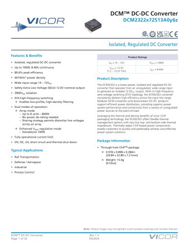 DCM2322x72S13A0y6z
32 Pages
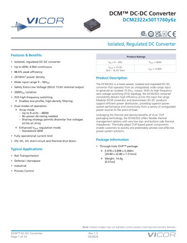 DCM2322x50T1760y6z
32 Pages
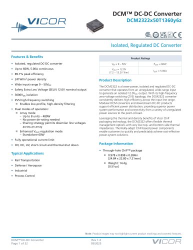 DCM2322x50T1360y6z
32 Pages
Archived catalogs
 Product Catalog
64 Pages
 Distributed Capture
1 Page

- DC power supply
- AC/DC power supply
- DC-DC converter
- Electronic filter
- Rack-mount power supply
- Programmable power supply
- DC/DC power supply
- Isolated DC-DC converter
- Industrial DC/DC converter module
- Low-pass electronic filter
- Single-output DC/DC converter module
- Chassis-mounted DC/DC converter module
- Power module
- SMD DC-DC converter
- Modular power supply
- EMI filter
- CE DC/DC converter module
- Current rectifier
- DC/DC converter for the automobile industry