- Company
- Products
- Catalogs
- News & Trends
- Exhibitions
PORTABLE BALANCER “BALANSET-1A”
1 /63Pages
PORTABLE BALANCER “BALANSET-1A”
1 /63Pages
Catalog excerpts

PORTABLE BALANCER “BALANSET-1A” A Dual-Channel PC-Based Dynamic Balancing System
Open the catalog to page 1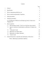
3. Device components and delivery set 5 4. Device structure and principle of operation 6 6.2.2 Installing the USB drivers and balancing software of the device 10 7.1 Main operating window. Correct use of the basic action buttons. 22 7.2 Input or correction of transformation coefficients of vibration sen- 24 7.4 Balancing in one plane (static) 27 7.5 Balancing in two planes (dynamic) 38 8. General instructions on operation and maintenance of the device 55 Annex 1 Balancing in operational conditions 61
Open the catalog to page 2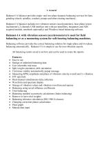
Balanset-IA balancer provides single- and two-plane dynamic balancing services for fans, grinding wheels, spindles, crushers, pumps and other rotating machinery. Balanset-1A balancer includes two vibration sensors (accelerometers), laser phase sensor (tachometer), 2-channels USB interface unit with per-amplifiers, integrators and ADC acquired module, notebook (optionally) and Windows based balancing software. Balancing software provides the correct balancing solution for single-plane and two-plane balancing automatically. Balanset-1A is simple to use for non-vibration experts. All balancing results...
Open the catalog to page 3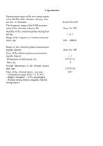
Measurement range of the root-mean-square value (RMS) of the vibration velocity, mm/ sec (for 1x vibration) The frequency range of the RMS measurement of the vibration velocity, Hz Number of the correction planes during balancing Range of the frequency of rotation measurement, rpm Range of the vibration phase measurement, angular degrees Error of the vibration phase measurement, angular degrees Dimensions (in hard case), cm, Mass, kg Overall dimensions of the vibrator sensor, mm, max Mass of the vibrator sensor, kg, max - Temperature range: from 5°C to 50°C - Relative humidity: < 85%, unsaturated...
Open the catalog to page 4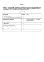
Balanset- 1A balancer includes two single-axis accelerometers, laser phase reference marker (digital tachometer), 2-channel USB interface unit with per-amplifiers, integrators and ADC acquired module, notebook (or other PC) and Windows based balancing software.
Open the catalog to page 5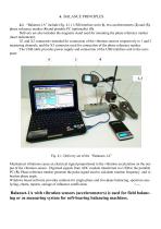
4. BALANCE PRINCIPLES 4.1. “Balanset-1A” include (fig. 4.1) USB interface unit (1), two accelerometers (2) and (3), phase reference marker (4) and portable PC (optionally) (5). Delivery set also includes the magnetic stand used for mounting the phase reference marker (laser tachometer). X1 and X2 connectors intended for connection of the vibration sensors respectively to 1 and 2 measuring channels, and the X3 connector used for connection of the phase reference marker. The USB cable provides power supply and connection of the USB interface unit to the computer. Fig. 4.1. Delivery set of the “Balanset-1A”...
Open the catalog to page 6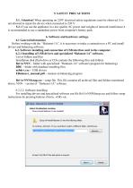
5. SAFETY PRECAUTIONS 5.1. Attention! When operating on 220V electrical safety regulations must be observed. It is not allowed to repair the device when connected to 220 V. 5.2. If you use the appliance in a low quality AC power and weights of network interference it is recommended to use a standalone power from computer's battery pack. 6. Software and hardware settings. 6.1 General information Before working with the “Balanset-1A”, it is necessary to make a connection to a PC and install drivers and balancing software. 6.2. Software installing and connection of USB interface unit to the computer....
Open the catalog to page 7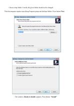
Choose setup folder. Usually the given folder should not be changed. Then the program requires specifying Program group and desktop folders. Press button Next. The window «Ready to Install» appears. Press button “Install
Open the catalog to page 8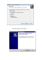
Then database engine will be installed.
Open the catalog to page 9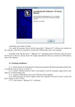
And finally press button «Finish» As a result all necessary drivers and the specialized “Balanset-1A” software are installed on the computer. After that it is possible to connect the USB interface unit to the computer. In further work with the device " “Balanset-1A”" operating system will know where the driver for this type of device is stored, and it will weight automatically when you connect the USB interface unit to the computer. 6.3.1. Install sensors on the inspected or balanced mechanism (Detailed information about how to install the sensors is given in Annex 1) 6.3.2. Connect vibration...
Open the catalog to page 12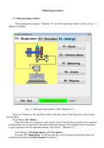
7 Balancing procedure. 7.1. Main operating window. When running the program “Balanset-1A” the main operating window, shown in Fig. 7.1, appears on display. Fig. 7.1. Main operating window of the “Balanset-1A” There are 9 buttons in the specified window with the names of the functions realized when click on them. 7.1.1. Button «F1-About». When this button is clicked (or, equivalently, the F1 function key pressed on the computer keyboard) the user can get brief information about the purpose of the program and, if necessary, to get acquainted with the operating manual of the device “Balanset-1A”....
Open the catalog to page 13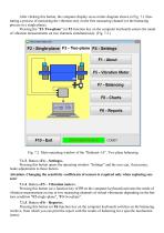
After clicking this button, the computer display saves mimic diagram shown in Fig. 7.1 illustrating a process of measuring the vibration only on the first measuring channel (or the balancing process in a single plane). Pressing the “F3-Two-plane” (or F3 function key on the computer keyboard) selects the mode of vibration measurements on two channels simultaneously. (Fig. 7.2.) Fig. 7.2. Main operating window of the “Balanset-1A”. Two plane balancing. 7.1.3. Button «F4 – Settings». Pressing this button opens the operating window “Settings” and the user can, if necessary, make adjustments to these...
Open the catalog to page 14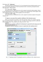
7.1.6. Button «F7 – Balancing». Pressing this button (or function key F7 on your keyboard) activates balancing mode in one or two correction planes depending on which measurement mode is selected by pressing the buttons "F2-single-plane", "F3-two-plane". 7.1.7. Button «F8 – Charts». Pressing this button (or F8 function key on the computer's keyboard) enables graphic vibrometer, the implementation of which displays on a computer screen simultaneously with the digital values of the amplitude and phase of the vibration graphics of its time function. 7.1.8. Button «F10 – Exit». Pressing this button...
Open the catalog to page 15- Adhesive tape
- Balancer
- Dynamic balancer
- Industrial adhesive tape
- Rotor balancing machine
- Handheld tachometer
- Non-contact tachometer
- Indicator stand
- Shaft balancing machine
- Machine monitoring vibration sensor
- Indicator stand with magnetic base
- MEMS vibration sensor
- Preventive maintenance vibration sensor
- Portable balancing device
- Rotary machine vibration sensor