- Catalogs
- VIA Technologies
- VIA Edge AI Developer Kit
VIA Edge AI Developer Kit
1 /10Pages

VIA Edge AI Developer Kit
1 /10Pages
Catalog excerpts

QUICK GUIDE
Open the catalog to page 1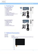
VIA Edge AI Developer Kit Quick Guide 1. Packing List Items for STK-VT6093-01A1 • 1 x SOM-9X20 module • 1 x SOMDB2 carrier board • 1 x VT6093 audio module • 1 x COM cable • 1 x AC adapter • 1 x Power cord US type • 2 x Antennas for Wi-Fi & Bluetooth • 1 x VT6093-CAM-T Camera-CSI converter board • 1 x 13MP CMOS camera module • 1 x FPC cable for CSI connector Items for STK-VT6093-00A1 • 1 x SOM-9X20 module • 1 x SOMDB2 carrier board • 1 x VT6093 audio module • 1 x COM cable • 1 x AC adapter • 1 x Power cord US type • 2 x Antennas for Wi-Fi & Bluetooth 2. Optional Accessories Touch Panel Part Number...
Open the catalog to page 2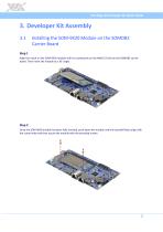
VIA Edge AI Developer Kit Quick Guide 3. Developer Kit Assembly 3.1 Installing the SOM-9X20 Module on the SOMDB2 Carrier Board Step 1 Align the notch on the SOM-9X20 module with its counterpart on the MXM 3.0 slot on the SOMDB2 carrier board. Then insert the module at a 30° angle. Step 2 Once the SOM-9X20 module has been fully inserted, push down the module until the standoff holes align with the screw holes and then secure the module with the provided screws.
Open the catalog to page 3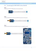
VIA Edge AI Developer Kit Quick Guide 3.2 Connecting the 13MP CMOS Camera Module Step 1 Connect the FPC cable to the VT6093-CAM-T (Camera-CSI converter board). Step 2 Connect the 13MP CMOS camera module to the VT6093-CAM-T (Camera-CSI converter board). Step 3 Connect the other end of the FPC cable to the MIPI CSI connector on the SOMDB2 carrier board.
Open the catalog to page 4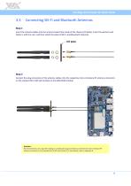
VIA Edge AI Developer Kit Quick Guide 3.3 Connecting Wi-Fi and Bluetooth Antennas Step 1 Insert the antenna cables into the antenna holes from inside of the chassis (I/O plate). Insert the washers and fasten it with the nuts, and then install the external Wi-Fi and Bluetooth antennas. Step 2 Connect the plug connectors of the antenna cables onto the respective micro-miniature RF antenna connectors on the onboard Wi-Fi+BT LGA module on the SOM-9X20 module. Reminder: We recommend to use a Jig when mating or unmating the plug connector to and from the micro-miniature RF antenna connector on the...
Open the catalog to page 5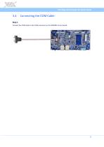
VIA Edge AI Developer Kit Quick Guide 3.4 Connecting the COM Cable Step 1 Connect the COM cable to the COM connector on the SOMDB2 carrier board.
Open the catalog to page 6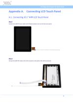
VIA Edge AI Developer Kit Quick Guide Appendix A. Connecting LCD Touch Panel A.1. Connecting 10.1" MIPI LCD Touch Panel Step 1 Connect the USB FPC touch cable to the flexible printed circuit on the LCD touch panel. Step 2 Connect the MIPI FPC cable to the LCD connector on the back of the LCD touch panel.
Open the catalog to page 7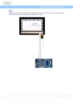
VIA Edge AI Developer Kit Quick Guide Step 3 Connect the other ends of the USB FPC touch cable and MIPI FPC cable to the P-Cap touch connector and MIPI DSI LCD panel connector respectively on the SOMDB2 carrier board.
Open the catalog to page 8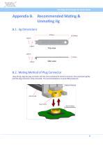
VIA Edge AI Developer Kit Quick Guide Appendix B. Recommended Mating & Unmating Jig B.1. Jig Dimensions B.2. Mating Method of Plug Connector Using the jig, align the plug connector onto the micro-miniature RF antenna connector. Then push down gently until the plug connector is fully connected. The recommended force must be 30N (maximum).
Open the catalog to page 9
Taiwan Headquarters 1F, 531 Zhong-zheng Road, Xindian Dist., New Taipei City 231 Taiwan 940 Mission Court Fremont, CA 94539, USA 3-15-7 Ebisu MT Bldg. 6F, Higashi, Shibuya-ku Tokyo 150-0011 Japan Tsinghua Science Park Bldg. 7 No. 1 Zongguancun East Road, Haidian Dist., Beijing, 100084 China Europe Email: [email protected]
Open the catalog to page 10All VIA Technologies catalogs and technical brochures
 AMOS-825-Android EVK v5.0.3
22 Pages
 VIA Mobile360 ADAS
2 Pages
 VIA Mobile360
2 Pages
 COMe-9X90
3 Pages
 EMIO-2550
2 Pages
 AMOS-3005
3 Pages
 AMOS-820
3 Pages
 VIA_EPIA-E900
2 Pages
 VIA_VTS-8589
2 Pages
 VIA_SOM-6X50
3 Pages
 VIA_QSM-8Q60
3 Pages
 ALTA DS 4K
2 Pages
 ARTiGO_A820
2 Pages
 VIA_ARTiGO_A600
2 Pages
 VIA_AMOS-825
2 Pages
 ETX-8X90-10GR
3 Pages
 EPIA-M920
2 Pages
 ARTiGO A1300
3 Pages
 CX700M (Single-Chip)
2 Pages
 VX900/H
2 Pages
 VX11H
VX11H2 Pages
 VIA C7®
2 Pages
 Eden® ULV Fanless
2 Pages
 Eden® X2 (Dual Core)
2 Pages
 QuadCore E-Series
2 Pages
 VAB-600 (Pico-ITX)
2 Pages
 VIA AMOS 800
2 Pages
 VAB-1000
2 Pages
 ARTiGO A900
2 Pages
 VAB-820
2 Pages
 VIPRO VP7910
3 Pages
 VAB-800
2 Pages
 VIA EPIA-M840
2 Pages
 VIA EPIA-M850
2 Pages
 VIA EPIA-M860
2 Pages
 VIA VX900
2 Pages
 VIA Nano X2
2 Pages
 VIA EPIA-P720
2 Pages
 VIA EPIA-P900
2 Pages
 VIA EITX-3000
4 Pages
 VIA EITX-3001
4 Pages
 VIA EITX-3002
5 Pages
 VIA EPIA EN
2 Pages
 VIA EPIA-M830
2 Pages
 VIA VB7001
2 Pages
 VIA VB8001
2 Pages
 VIA VB8004
2 Pages
 VIA CN700
2 Pages
 VIA CN896
2 Pages
 VIA VX800
2 Pages
 VX855
VX8552 Pages
 VIA EPIA-M900
2 Pages
 VIA QuadCore Flyer
2 Pages


