


Introduction to KM6 Subracks

Introduction to KM6 Subracks
The document provides a detailed overview of KM6 subracks, emphasizing their precision and versatility in supporting and guiding PCBs. It highlights the importance of extrusion technology for accuracy and discusses the subrack's role in providing RFI, shock, vibration, and ESD protection.
RFI protection is achieved through the use of covers, EMC contact fingers, and conductively finished parts, forming a Faraday cage for high signal attenuation. Alternatives include board-level design changes or screened modules.
Protection against shock and vibration is provided by secure card guides and robust mounting solutions. Custom solutions are typically based on the subrack principle.
ESD protection is ensured through grounding clips and front panel grounding. Alternatives include anti-static packaging and connector pin discharge.
The subrack system is highly versatile, allowing for configurable space to accommodate various heights, widths, and orientations without the need for custom tooling.
The KM6-II subrack system is compatible with DIN 41494 and IEC 60297-3 standards. It is robust, versatile, available in multiple sizes and configurations, and supported by a range of accessories.
Designed for modern industrial applications, the KM6-HD subrack system meets IEEE 1101.10/11 standards, offering features like RFI shielding and ESD protection, suitable for VME64x and CompactPCI applications.
The document details Eurocard dimensional criteria, emphasizing interchangeability and standardization according to IEC 60297-3 and IEEE 1101.10/11 standards. It includes critical dimensions for Eurocards and subrack configurations.
The document outlines the dimensional criteria for subracks based on IEEE 1101.10/11 standards. It specifies dimensions for rear plug-up units and connectors, emphasizing adherence to standards like IEC 603-2 and IEC 1076-4-x for attachment planes and locking interfaces.
The guide discusses EMC screening for subracks, noting that empty enclosures are not subject to EMC performance regulations. It emphasizes limiting hole sizes and slot lengths to improve electrical field performance, while material and thickness are crucial for magnetic field performance. EMC gaskets are suggested to enhance screening performance, with data provided on the effect of finger spacing on attenuation.
The document addresses the impact of shock and vibration on subracks, particularly in mobile and industrial environments. It discusses factors affecting stability, such as weight distribution and construction rigidity, and recommends using positive retention for heavy components and considering material additions to maintain dimensional standards.
Aluminium is highlighted for its benefits in subrack construction, including weight reduction and heat conduction. The document details anodizing and chromate conversion processes for corrosion resistance. It also discusses the use of steel for rigidity and moulded plastics for complex components, emphasizing fire resistance and chemical solvent susceptibility. The trend towards stainless steel for EMC seals is noted due to environmental concerns with Beryllium Copper.
Catalog excerpts

VEROTEC Electronics Packaging
Open the catalog to page 1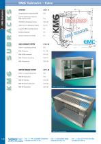
OVERVIEW 1.03-1.14 An introduction to subracks & KM6 Eurocard dimensional criteria for KM6 subrack systems IEEE 1101.10/11 dimensional criteria A guide to EMC screening subracks Subrack materials and finishes TecServ+ (customising service) KM6-II Subrack piece parts TecServ+ (customising service) KM6-HD Subracks 1.44-1.46 KM6-HD Subrack piece parts
Open the catalog to page 2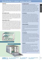
An introduction to subrack systems and KM6 INTRODUCTION Fully compatible with DIN 41494 part 5 and IEC 60297-3, KM6-II subracks are strong, versatile and easy to assemble. All tiebars have two screw fixing positions making the construction robust yet accurate and well suited to light and medium duty applications. The range is extensive, offering 3U, 4U, 6U and 9U heights in width of 24, 42, 60 & 84HP and depths of 160, 240, 300, 360 & 420mm. KM6-II Subracks are supplied either in kit form or individual component parts and are complimented by a wide range of accessories, including EMC conversion...
Open the catalog to page 3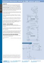
Eurocard dimensional criteria for KM6 subrack systems INTRODUCTION KM6 Subracks are designed around a number of dimensional standards that aim to provide a basic level of interchangeability between different versions and between manufacturers of similar systems. The basis is the DIN41494 Eurocard standard. The dimensions for the housing of Eurocards are described in IEC60297 section 3 SC48D. Plug-in units are modular in concept and are based on the first card position being 3,27mm from the left hand datum line of the working aperture; subsequent card positions are on multiples of 5,08mm (1HP)...
Open the catalog to page 4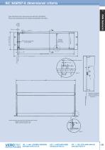
IEC 60297-3 dimensional criteria 1 KM6 Subracks First fastening location These illustrations show dimensions extracted from IEC 60297-3. They are not comprehensive, but should prove generally informative PCB Positions incrementally by 5,08 multiples Centre line first PCB Pitch line Rear attachment plane Scrap view of 6U showing dimensions available for centre rear extrusion with 6U plug-in units Subrack dimensions shown are for 3U x 84HP and single Eurocards Heights increment by 44,45mm (1U) Widths increment by 5,08mm (1HP) Pitch line
Open the catalog to page 5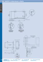
Motherboard fixing centres 122,5 Front panel fixing centres 122,5 *Rear attachment plane (i.e. Connector Mounting Face) For DIN 41612 types BCDMQRS For types FGUV add 10mm Front attachment plane 175,24 * Section 'A-A' DIN 41612 connector mounted on motherboard Alternative for direct mounting of DIN 41612 connectors Fixing holes incrementing on multiples of 5,08 as required 84 x 5,08 Motherboard dimensions showing Type 'B' & 'C' DIN 41612 connector positions Front view Pitch line Front attachment plane Pitch line Limit of component mounting area Fixing holes on multiples of 5,08 'U' Pitch line...
Open the catalog to page 6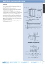
IEEE 1101.10/11 dimensional criteria 1 INTRODUCTION Box type plug in unit Injector / Extractor operating feature IEEE110.10 was driven by a number of requirements: The standardisation of EMC front panel geometry to ensure compatibility between various manufacturers’ products. EMC seals The standard also addresses the problems of electrostatic protection and a need to code plug-in units to prevent incorrect plug-up, where such actions could have catastrophic results (in particular in live insertion situations). Infill (blank) panel Coding / ESD feature Injector / Extractor IEEE1101.11 standardises...
Open the catalog to page 7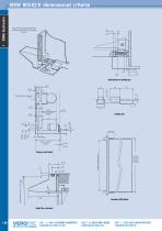
Typical plug-in unit showing injector / extractor coding, ESD and front panel geometry IEEE 1101.10/11 dimensional criteria Protective cover (optional) Usable component space Plug-in unit detail
Open the catalog to page 8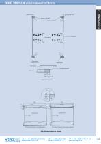
IEEE 1101.10/11 dimensional criteria 1 KM6 Subracks Subrack front view Board type Plug-in unit Rear View Alignment / ESD feature B C Empty Printed Board Keying Options Keying chamber (subrack mounted) Keying chamber front panel Front Extrusion Front attachment plane Guide rail 10 60 Guide rail ESD contact area Component side Component side Rear ESD contact breaks before connector engagement ESD contact maintained during connector engagement PCB ESD Contact strips top / bottom
Open the catalog to page 9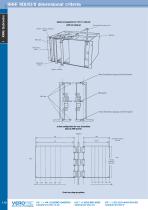
IEEE 1101.10/11 dimensional criteria Typical arrangement of 1101.11 subrack with rear plug-up Rear (transition) plug-up unit Injector / extractor operating feature Midplane Infill (blank) panel Coding ESD feature Injector / extractor Rear (transition) plug-up unit/front panel Front (transition) plug-up unit/front panel In line configuration for rear (transition) plug-up EMC panels. Midplane Db Dimensions refer to 160 unit Front rear plug-up options
Open the catalog to page 10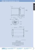
IEEE 1101.10/11 dimensional criteria 1 Rear plug-up dimensions (160 shown) Spacer (user defined) Rear free connector Rear fixed connector Front fixed connector Inspection Dimension Rear (transition) plug up detail 3U shown ESD / Electrical safety ground Frame mounted coding / ESD / location / electrical safety ground feature
Open the catalog to page 11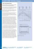
A GUIDE TO THE EMC SCREENING SUBRACKS A guide to EMC screening subracks Whilst KM6-HD is designed / supplied with full line capability as standard, KM6-II subracks can be retrospectively screened by the addition of covers, gaskets, front panels and associated components – as detailed in the relevant section of this catalogue. Please note that any reference in this section to attenuation figures is theoretical, and examples have been obtained under laboratory conditions only. By its nature, an empty enclosure does not fall within the scope of any EMC performance regulation, since all the existing...
Open the catalog to page 12
The increasing use of electronics in such applications as mobile, roadside, factory and earthquake environments has led to an increased awareness of the effects of shock and vibration on full systems. The use of subracks in these conditions is generally limited by a number of factors. 1) The loading - both total weight and its distribution; increased height to some extent improves the vertical stability; increasing width adversely affects its resistance to vibration in the vertical axis and the deflection of horizontal components; increasing depth encourages ‘parallelogramming’ in sideways shock...
Open the catalog to page 13All Verotec catalogs and technical brochures
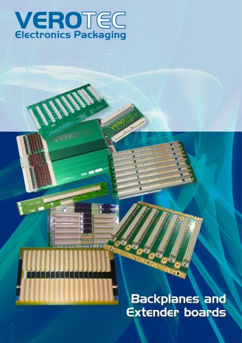 BackPlanes And Extender Boards
12 Pages
 CompactPCI Power Supplies
25 Pages
 19in Racks & Accessories
33 Pages
 19in Rack Cases
10 Pages
 Enclosure Accessories
5 Pages
 KM6-II Subracks
26 Pages
 KM6 HD Subracks
15 Pages
 KM6 Front Panels & Modules
23 Pages
 Eurotec Caseframes
9 Pages
 Diplomat Cases
21 Pages
 VEROtec Cases
14 Pages
 Total Access Cases
4 Pages
 LBX Cases
4 Pages
 19? Racks and Accessories
33 Pages
 19" Rackcases
10 Pages
 Power Supplies
32 Pages
 Backplanes & Extender Boards
12 Pages
 Thermal Solutions
8 Pages
 Integrated Systems
26 Pages
 Compact PCI Power Supplies
25 Pages
 26-Power
54 Pages
 KM6 EC Subracks
4 Pages
 Connectors to DIN 41612
8 Pages
 KM6 RF Subracks
29 Pages
Archived catalogs
 KM6 Caseframe
8 Pages
- Power supply unit
- DC power supply
- AC/DC power supply
- Rectangular housing
- Plastic housing
- CE power supply
- Metal box
- Rack-mount power supply
- Electrical cabinet
- Floor-mounted electrical cabinet
- Rack-mount chassis
- Backpanel
- Rack-mount enclosure
- EMC enclosure
- Steel box
- 19" chassis
- Industrial chassis
- 19" rack housing
- PICMG backplane
- Desktop computer enclosure