


V2I

V2I
The V2I module is a cost-effective, high-quality device designed to convert DC voltage measurements into current loop signals. It is a compact two-wire transmitter that outputs a proportional 4-20mA control signal, powered by a local DC supply.
Electrical Specifications
- Accuracy: ±0.2% of reading
- Max total phase shift at 60Hz: < 0.05°
- Max input delay (120kHz versions): < 2.8 μs
- Integrated sensor noise: < 50 μA
- Total power consumption: 1.5W
- Input Dynamic Range: ±5V or ±10V
Mechanical Specifications
- Mounting Type: DIN Rail
- Connectivity: RJ45 Ethernet jack
- Dimensions: 1.4” x 1.4” x 4.5”
- Weight: 198 g (7.0 oz)
Performance
- Input-Output non-linearity: < 70 ppm
- Output current: 4-20mA
- Gain temperature drift: ±50 ppm/°C
- Common mode rejection at 60Hz: 105 dB
- Bandwidth: 500kHz
- Power Supply Voltage: 5V, 9V, 15V, or 24V
- Output type: Current loop
- Differential Input impedance: > 10 MΩ
- Common mode impedance: > 2 GΩ || 4pF
- Maximum Output Load: 500Ω
Environmental Conditions
- Operating temperature: –25 to 70 °C
- Storage temperature: –40 to 80 °C
Specifications
Signals are connected via the RJ-45 and routed according to the wiring diagram. The module mounts on standard NS-35 or NS-32 DIN rails, offering ease of use and flexibility.
Hardware Description
The V2I is a 4-channel Voltage to Current Transducer. It is not a safety device and should not be used as such. It lacks self-checking redundant circuitry, and failure could result in hazardous conditions.
Standards and Certifications
- CE Certified
Hardware Configuration
- Connect the input signal securely into the RJ-45 connector.
- Connect the output terminals to the inputs of your data acquisition unit.
- Connect an external power source with at least 0.2A continuous current and 0.4A surge during start-up.
Mechanical Dimensions
The module's dimensions are specified for proper installation and integration.
Catalog excerpts

V2I 4 channel Voltage to Current Transducer The V2I module has been designed to provide low-cost and high-quality translation of voltage measurements into current loop signals. The V2I is a compact two-wire transmitter that converts a process level DC voltage input to a proportional 4-20mA control signal. Power is received a local DC supply when using a two wire connection. SPECIFICATION Eletrical Accuracy (percentage of reading) Max total phase shift at 60Hz Max Input delay (120kHz versions) Integrated sensor noise (Referenced to input) Total power consumption Input Dynamic Range Input-Output non-linearity Output current Gain temperature drift Common mode rejection at 60Hz Bandwidth Power Supply Voltage Output type Differential Input impedance Common mode impedance Maximum Output Load Mounting Type Connectivity (Connector for power in and signal out to/ from the sensor) Outer Dimensions Weight The voltage input connector is located at the top of the module in the figure bellow. A connector that servers to power the unit, ground and output the sensor signal lay along the bottom. Environmental Operating temperature Storage temperature HARDWARE DESCRIPTION V2I connectivity The V2I module is designed to mount on standard NS-35 or NS32 DIN rails with minimal preparation, providing users ease of use and flexibility. Wiring diagram Signals are connected into the V2I via the RJ-45 and routed as the wiring diagram above.
Open the catalog to page 1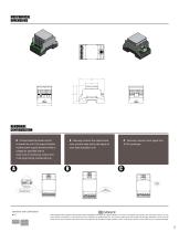
MERCHANICAL DIMENSIONS HARDWARE CONFIGURATION A. Connect external power source to power the unit. For proper functioning the power supply should provide a voltage as specified with at least 0.2A of continuous current and 0.4A surge during module start-up. B. Securely connect the output terminals, and the other end to the inputs of your data acquisition unit C. Securely connect input signal into RJ-45 connector THIS SENSOR IS NOT A SAFETY DEVICE AND IS NOT INTENDED TO BE USED AS A SAFETY DEVICE. This sensor is designed only to detect and read certain data in an electronic manner and perform no...
Open the catalog to page 2All Verivolt catalogs and technical brochures
 IsoBlock I-FG-4c
2 Pages
 Entube QE
2 Pages
 Encore
2 Pages
 Entube SE
2 Pages
 Entube Z
2 Pages
 Esol TE-MV
2 Pages
 IsoBlock Q-4c
2 Pages
 Envoy SC
2 Pages
 Entube DE
2 Pages
 Entube DE-HB
2 Pages
 Entube TE
2 Pages
 IsoBlock C-4c
2 Pages
 IsoBlock P-1c
2 Pages
 IsoBlock I-FG-1c
2 Pages
 IsoBlock V-4c
2 Pages
 Entube DE-HB-S
2 Pages
 IsoBlock C
2 Pages
 IsoBlock V-1c
2 Pages
 IsoBlock Q
2 Pages


