IsoBlock V-1c
1 /2Pages

IsoBlock V-1c
1 /2Pages
Catalog excerpts

IsoBlock V Galvanicaly Isolated Differential Voltage Sensor The IsoBlock V-1c has been designed to provide high-quality isolated differential voltage measurements for aplications requiring scaling of high voltages, as well as superior isolation. Each IsoBlock V unit hosts an isolated channel that can be connected to separate measurement sources while providing a range of functional coverage up to 1500V. The input has its own isolated reference, and can be configured to suit user needs. The output signal from the IsoBlock unit is referenced in respect to the ground channel of the user’s data acquisition system. Verivolt designs its IsoBlock V modules with consideration for user great flexibility, and low power consumption. Integrated sensor noise (Referenced to input) Gain (Using 10V standard output voltage) Differential input dynamic range Channels per module Accuracy (percentage of reading) Max total phase shift at 60Hz Max Input delay (120kHz versions) Isolation voltage from primary side to secondary side Input-Output non-linearity Output voltage Gain temperature drift Common mode rejection at 60Hz Power Supply Voltage Output type Withstanding common mode surge voltage Output Offset Voltage (Referenced to output) Withstanding differential mode surge voltage Differential Input impedance Insulation impedance Output impedance Mounting Type Connectivity (Connector for power in and signal out to/ from the sensor) Outer Dimensions Channels Weight Spring Cage connector HARDWARE DESCRIPTION The IsoBlock V module is designed to isolate and scale down high voltages found in industrial enviroments. The end result is a signal ready to connect to any data acquisition system, while galvanically isolating the source from it. Each channel of the IsoBlock module has a galvanic isolation from the input to the output that can eliminate large common mode voltages. In addition to that, each channel also has a protection stage at the input that guards it from surges. Following the input surge protection stage, there is an amplification stage that brings the input signal to a ±10V range. This signal is modulated into a magnetic field, and then transferred across a galvanic barrier. A demodulating stage recovers the original signal, followed by an anti-aliasing filter and a conditioning stage to output a ±10V differential pair. The figure below shows a block diagram of the process decribed above. < 130 ppm ±10 V ±50 ppm/°C 112 dB 8V to 28 V Differential pair < ±500 µV > 10 MΩ > 10 GΩ || 2pF 100Ω IsoBlock V single channel block diagram. Environmental Operating temperature Storage temperature - The isolation barrier of every device is tested with a 5 second partial discharge of 1800V for 5 seconds, with a detection threshold of 150pC. - Withstanding common mode surge voltage is 2 seconds half sinewave. - Withstanding differential mode surge voltage is 4 seconds half sinewave.
Open the catalog to page 1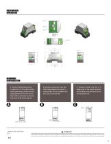
twisted pair to the output terminals, and the other end to the inputs of your data acquisition unit . Signal inputs A. Connect external power source to power the unit. For proper function- ing the power supply should provide a voltage between 8V and 28V with at least 0.25A of continuous current and 0.5A surge during module start-up. B. Securely connect wire in the 20-6 AWG range between the source of measurement and an available IsoB- lock's input screw terminal. Standards and Certifications ^ DANG ER • CE THIS SENSOR IS NOT A SAFETY DEVICE AND IS NOT INTENDED TO BE USED AS A SAFETY DEVICE. This...
Open the catalog to page 2All Verivolt catalogs and technical brochures
 IsoBlock I-FG-4c
2 Pages
 Entube QE
2 Pages
 Encore
2 Pages
 Entube SE
2 Pages
 V2I
V2I2 Pages
 Entube Z
2 Pages
 Esol TE-MV
2 Pages
 IsoBlock Q-4c
2 Pages
 Envoy SC
2 Pages
 Entube DE
2 Pages
 Entube DE-HB
2 Pages
 Entube TE
2 Pages
 IsoBlock C-4c
2 Pages
 IsoBlock P-1c
2 Pages
 IsoBlock I-FG-1c
2 Pages
 IsoBlock V-4c
2 Pages
 Entube DE-HB-S
2 Pages
 IsoBlock C
2 Pages
 IsoBlock Q
2 Pages


