IsoBlock Q Isolation Amplifier
1 /2Pages

IsoBlock Q Isolation Amplifier
1 /2Pages
Catalog excerpts
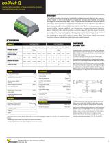
Isolated Signal Amplifier for Superconducting magnets Quench Detection and Location The IsoBlock Q module was designed to isolate the voltage across cable segments of a superconducting magnet, as well as coils, half and full magnets. By placing multiple IsoBlock sensors along the length of a superconducting cable, a time-of-flight technique can be used to locate a quench origin. Also, Isoblock sensors can be placed across larger symmetrical segments of a magnet to detect when the magnet starts quenching from superconducting state. Each channel amplifies and magnetically modulates its input signal across a galvanic barrier. This results in 1200V sustained and 4200V surge isolation from channel-to-channel and channel-toground. In addition to that, each channel has a protection stage at its input that allows it to sustain the voltage spike generated during the magnet energy extraction. At the output of each isolation channel there is an anti-aliasing filter and a conditioning stage to output a ±10V signal. The compact form factor of the IsoBlock Q module allows users to setup high channel density monitoring systems, making it also ideal for extended magnet networks. HARDWARE DESCRIPTION High Range Model Integrated sensor noise (Referenced to input) Gain (10V standard output voltage) Differential input dynamic range Accuracy (percentage of reading) Max total phase shift at 60Hz Max Input delay (120kHz versions) Input-Output non-linearity Output voltage Gain temperature drift Common mode rejection at 60Hz Power Supply Voltage The IsoBlock Q module is designed to measure small differential voltages induced in superconducting magnets, while isolating the data acquisition system from their source. Each channel has a galvanic isolation from the input to the output that eliminates large common mode voltages. In addition to that, each channel also has a protection stage at the input that protects the channel from large surge voltages, such as the once experienced when a superconducting magnet quenches from superconducting state and all the energy stored in the magnet has to be dissipated. Following the input surge protection stage, there is an amplification stage that brings the input signal to a ±10V range. This signal is modulated into a magnetic field, and then transferred across a galvanic barrier. A demodulating stage recovers the original signal, followed by an anti-aliasing filter and a conditioning stage to output a ±10V differential pair. Isolation voltage from primary side to secondary side Withstanding common mode surge voltage Output Offset Voltage (Referenced to output) Withstanding differential mode surge voltage Differential Input impedance Insulation impedance Output type Output impedance Mounting Type Connectivity (Connector for power in and signal out to/ from the sensor) Outer Dimensions Clamp cagge & Spring gage Environmental Operating temperature Storage temperature Channels Weight - The isolation barrier of every device is tested with a 5 second partial discharge of 1800V for 5 seconds, with a detection threshold of 150pC. - Withstanding common mode surge voltage is 2 seconds half sinewave. - Withstanding differential mode surge voltage is 4 seconds half sinewave. IsoBlock Q single channel block diagram. 50 Ω The input amplification stage has a selectable gain feature that allows users to select one of 5 different input ranges for each channel. There are currently two different set of input dynamic ranges offered by Verivolt; one has a set of input ranges between 10mV to 2V (Low Range), and the other has a set of input ranges between 1V and 20V (High Range). There is a 2-row, 8-position header on each channel of the IsoBlock Q that is used for gain selection. Place the jumpers that come with the module to select the dynamic range of each channel. The High-Gain sensor has input ranges 10mV, 40mV, 150mV, 500mV and 2V, while the Low-Gain sensor has input ranges 1V, 2V, 5V
Open the catalog to page 1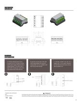
A. Connect external power source to power the unit. For proper function- ing the power supply should provide a voltage between 7V and 28V with at least 0.25A of continuous current and 0.5A surge during module start-up. B. Securely connect wire in the 20-6 AWG range between the source of measurement and an available IsoB- lock's input screw terminal. twisted pair to the output terminals, and the other end to the inputs of your data acquisition unit Standards and Certifications ^ DANG ER • CE THIS SENSOR IS NOT A SAFETY DEVICE AND IS NOT INTENDED TO BE USED AS A SAFETY DEVICE. This sensor is designed...
Open the catalog to page 2All Verivolt catalogs and technical brochures
 IsoBlock I-FG-4c
2 Pages
 Entube QE
2 Pages
 Encore
2 Pages
 Entube SE
2 Pages
 V2I
V2I2 Pages
 Entube Z
2 Pages
 Esol TE-MV
2 Pages
 IsoBlock Q-4c
2 Pages
 Envoy SC
2 Pages
 Entube DE
2 Pages
 Entube DE-HB
2 Pages
 Entube TE
2 Pages
 IsoBlock C-4c
2 Pages
 IsoBlock P-1c
2 Pages
 IsoBlock I-FG-1c
2 Pages
 IsoBlock V-4c
2 Pages
 Entube DE-HB-S
2 Pages
 IsoBlock C
2 Pages
 IsoBlock V-1c
2 Pages
 IsoBlock Q
2 Pages

