Entube TE
1 /2Pages

Entube TE
1 /2Pages
Catalog excerpts
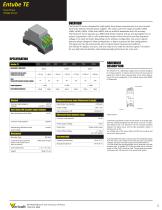
Entube TE Three Phase Voltage Sensor The Entube-TE series is designed for high quality three-phase measurements in a very compact form factor without need for power supplies. This series covers the ranges of ±100V, ±200V, ±300V, ±400V, ±500V, ±750V and ±1000V, with up to 85kHz bandwidth and 0.2% accuracy. The Entube-TE sensor operates as a differential divider network with an anti-aliasing filter on its output. It generates a ±5V or ±10V scaled down version of the line-to-line and line-to-ground voltage on its input terminals. Depending on the software configuration, the sensor outputs phase-to-phase voltages for Delta configuration, or phase-to-ground for Wye configurations. This signal can then be processed by most computer based measurement platforms. One Entube-TE replaces 3 sensors, and only requires one cable for all three signals. This allows for very high channel densities, while delivering high performance for a low cost. Integrated sensor noise (Referenced to input) Gain (Using 10V standard output voltage) Input Impedance The Entube-TE is a differential voltage down-converter designed for 3-phase systems. It outputs all line-to-line and line-to-ground signal pairs. Delta or Wye measurements can be made depending on the input configuration of the digitizer being used (NRSE or Differential). Line Output Impedance HARDWARE DESCRIPTION Integrated sensor noise (Referenced to input) Accuracy (percentage of reading) Gain (Using 10V standard output voltage) Max total phase shift at 60Hz Common mode rejection Withstanding differential mode surge voltage Input-Output non-linearity Output voltage Gain temperature drift Differential input dynamic range Signal Layout Common mode rejection Connectivity (Connector for power in and signal out to/ from the sensor) Outer Dimensions Weight Power Supply Voltage Output type Output Offset Voltage Mechanical Mounting Type Single-ended signal < ± 10µV (on ±10V signal) Environmental Operating temperature Storage temperature The three input phases connect to the sensor via a Spring-cage, while the conditioned signals from the sensor come out on a standard Ethernet jack. The Entube-TE can be mounted anywhere between the signal source and the data acquisition system. A female-screw on the low voltage side of the sensor allows for DIN rail mounting, and serves as a safety ground. A standard Ethernet cable is used to carry the conditioned signals from the sensor. The orange, brown and blue pairs carry phase voltages; the green connects to ground and DAQ reference. To avoid limiting the signal bandwidth and to eliminate cross-talk between pairs, a shielded STP Ethernet cable with a maximum length of 100m (330’) should be used. This will keep good reso
Open the catalog to page 1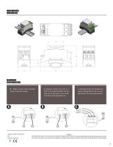
MERCHANICAL DIMENSIONS HARDWARE CONFIGURATION A. Safely connect Data Acquistion ground to ground of sensor. Standards and Certifications ● CE ● RoHS Compliant B. Securely connect one end of a RJ45 to the output terminals, and the other end to the inputs of your breakout board or data acquisition unit C. Securely connect wire between the source ofmeasurement and an available Entube TE’s input screw terminal. THIS SENSOR IS NOT A SAFETY DEVICE AND IS NOT INTENDED TO BE USED AS A SAFETY DEVICE. This sensor is designed only to detect and read certain data in an electronic manner and perform no use...
Open the catalog to page 2All Verivolt catalogs and technical brochures
 IsoBlock I-FG-4c
2 Pages
 Entube QE
2 Pages
 Encore
2 Pages
 Entube SE
2 Pages
 V2I
V2I2 Pages
 Entube Z
2 Pages
 Esol TE-MV
2 Pages
 IsoBlock Q-4c
2 Pages
 Envoy SC
2 Pages
 Entube DE
2 Pages
 Entube DE-HB
2 Pages
 IsoBlock C-4c
2 Pages
 IsoBlock P-1c
2 Pages
 IsoBlock I-FG-1c
2 Pages
 IsoBlock V-4c
2 Pages
 Entube DE-HB-S
2 Pages
 IsoBlock C
2 Pages
 IsoBlock V-1c
2 Pages
 IsoBlock Q
2 Pages


