- Catalogs
- Velocio Networks
- vLink Extender Module Pair
vLink Extender Module Pair
1 /1Page

vLink Extender Module Pair
1 /1Page
Catalog excerpts
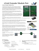
vLink Extender Module Pair vLink Extender Module Pair vLink Extenders are sold as a pair. The pair includes one module for connection to the vLink output connection of the higher level (in the system tree) Branch or Branch Expansion PLC, and a second module for connection to the vLink input connection to the lower level Branch Expansion. By using vLink Extenders, a vLink connection between Velocio PLCs can be extended up to 100 meters (328 feet). The only difference between the two module is termination resistors. Termination resistors are designed into the modules to eliminate signal reflection on the communication lines. A pair of vLink Extenders is pictured on the right. The Extender labeled vLink Out (black label) connects to the vLink cable that is plugged into the Branch, or higher level Branch Expansion unit. The vLink In (white label) connects to the vLink cable plugged into the Branch Expansion’s vLink input port. Each Extender module has an 8 position terminal block socket and is supplied with a mating plug that is the same as used with Velocio PLCs. The mating plug is shown on the right. It is recommended that you acquire standard CAT5e cable to span the distance between the two PLCs. The CAT5e cable must be connected to the 8 position plugs on each end. The cable connections to the plugs will be identical on each end Strip the cable outer covering back approximately 1.25 inchs to expose the eight wires in the cable (4 pairs). Untwist the pairs, so that you’ve got eight individual color coded wires. Strip the insulation from each wire to expose about 1/8 inch length of 22AWG solid copper wire. Push the wire into a plug connector, which comes with the Extenders, in the sequence shown on the right. Tug on each wire to confirm that it is pushed in and captured. Repeat for the other end of the cable. If you make a mistake and put the wrong wire in a position, use a Velocio connector tool (screwdriver) to extract the wire. Push the blade into the rectangular hole associated with the wire position, with the wide orientation of the blade aligned with the wide length of the hole. This will release the connector’s spring clamp. Gently pull the wire out and then remove the blade. shown with large, circular holes up A complete vLink extension is shown on the right. These modules mount to a 15mm DIN rail, or over two spaced screws. The DIN rail mount of similarly mounted modules, is illustrated on the right. Part Number vLXpair Extender Pair Cable Connectors vLink connection to PLC : vLink cable socket extension cable connection : Terminal type Socket connectors and Spring cage capture plug Terminal spacing 2.50mm Wire AWG 26 to 20 AWG * recommend CAT5e cable Max connection distance :100 meters (328 ft) Mounting : DIN rail option : standard 15mm DIN rail (snap) Mounting screw option : over two #6 screws, placed 1.5 inches apart
Open the catalog to page 1All Velocio Networks catalogs and technical brochures
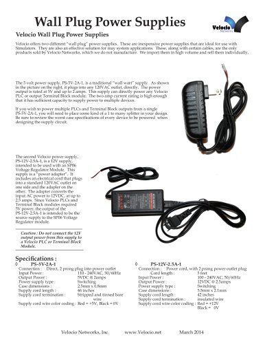 Wall Plug Power Supplies
1 Page
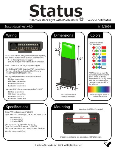 Status
1 Page
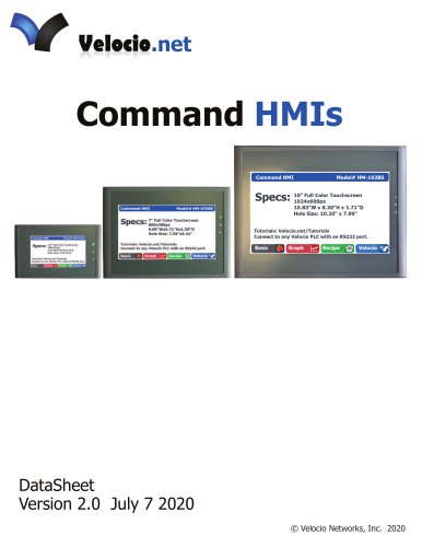 Command HMIs
6 Pages
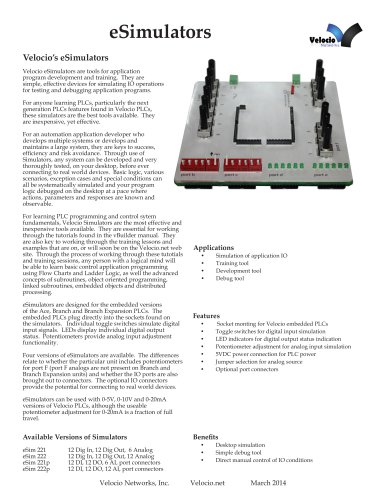 eSimulators
4 Pages
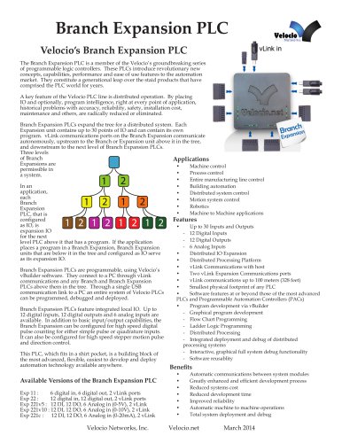 Branch Expansion PLC
6 Pages
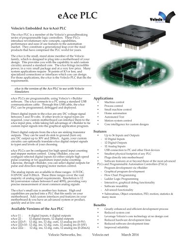 eAce PLC
5 Pages
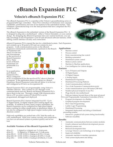 eBranch Expansion PLC
6 Pages
 eBranch PLC
6 Pages
 Branch PLC
13 Pages
 Ace PLCs
20 Pages