- Catalogs
- VELMEX, Inc.
- Velmex Rotary Table Manual/Motor Replacement
Velmex Rotary Table Manual/Motor Replacement
1 /1Page

Velmex Rotary Table Manual/Motor Replacement
1 /1Page
Catalog excerpts
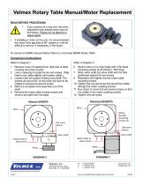
Velmex Rotary Table Manual/Motor Replacement READ BEFORE PROCEEDING • • If you receive as a new unit, the worm adjustment has already been done at the factory. Please do not attempt to adjust again. If installing a motor on the unit, it is recommended the motor have two flats at 90° angles or it will be difficult to remove, if necessary, in the future. To convert an A5990 manual Rotary Table to a motorized B5990 Rotary Table: Conversion Instructions Refer to Diagram 1 1. Remove cover (if needed) from right side of table covering set screw access. 2. Look in opening to locate the two set screws. (May need to turn table slightly until screws visible.) 3. Loosen both set screws holding knob shaft. The screws are set at 90º, so the knob will have to be rotated to access the second screw. 4. Slide the complete knob assembly out of the shaft. 5. Remove the motor plate to base screws and remove the plate from the base. 6. Mount motor on to motor plate with 4 flat head mounting screws (4-40 thread x .500 long). 7. Slide motor shaft into drive shaft with the flats positioned against the set screws. 9. Reposition and tighten the two motor plate mounting screws. 10. Tighten the one set screw that should be visible through the motor coupling access. 11. Run motor to move 2nd set screw in place so that it is visible in the motor coupling access. 12. Tighten 2nd set screw. Motor to plate mounting screws (4) Set screw access. Drive shaft Drive shaft Motor plate to base screws Motor plate to base screws 7550 State Routes 5 & 20 Bloomfield, NY 14469-9389 www.velmex.com [email protected] Positioning Systems for Science and Industry Page 1
Open the catalog to page 1All VELMEX, Inc. catalogs and technical brochures
 Limit Switches
7 Pages
 Rotary-incremental-encoder
3 Pages
 Velmex Catalog
149 Pages
 Linear and Rotary Encoders
5 Pages
 XSlide Spec Overview
8 Pages
 VRO™ Digital Readout Spec Sheet
10 Pages
 Rotary-Encoder-Lead-Screw
12 Pages
 Magnetic_Encoder
1 Page
 Inductive_LinearTapeEncoders
15 Pages
 PK296B2A-SG36,_StepperMotor
3 Pages
 PK296B2A-SG18,_StepperMotor
3 Pages
 PK296B2A-SG10,_StepperMotor
3 Pages
 PK264-03A,_StepperMotor
2 Pages
 PK243A1A-SG18,_StepperMotor
2 Pages
 Lead Screw Translation
6 Pages
 VXM Full Command Summary
3 Pages
 VXM Controller
8 Pages
 UniSlide
16 Pages
 TA System 7-1-14 Rev C
4 Pages
 BiSlide Side Knob
2 Pages
 BISlide Catolog
16 Pages


Archived catalogs
 VRO Overview
5 Pages


- ERA-SIB electric motor
- DC electromotor
- ERA-SIB rotary encoder
- ERA-SIB positioning stage
- ERA-SIB measuring system
- Incremental encoder
- Lifting table
- ERA-SIB linear positioning stage
- Incremental rotary encoder
- Digital indicator
- Stationary lift table
- Motorized positioning table
- ERA-SIB precision positioning stage
- Optical rotary encoder
- Motor controller
- Hollow-shaft rotary encoder
- Magnetic rotary encoder
- Electric rotary table
- Stepper motor