 Website:
VELMEX, Inc.
Group: Velmex
Catalog excerpts

Length Measuring System AMOSIN Technology Linear Motion in its Simplest Form
Open the catalog to page 1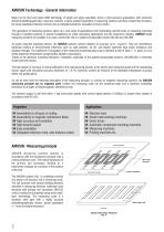
AMOSIN Technology - General information Based on the tried and tested AMO technology of length and angle acquisition where a high precision graduations with structures etched photolithographically in steel are scanned, a future-oriented generation of measuring systems has been created that incorporates newly developed inductive sensors and an integrated electronic evaluation circuitry (ASIC). This generation of measuring systems opens up a vast range of applications from demanding machine tools or measuring machines through to handling systems or special installations for metal machining...
Open the catalog to page 2
The relative movement in measurement direction between the sensor structure (in the scanning head) and measuring scale periodically changes the mutual inductance of the individual coils and generates two sinusoidal, 90°-phase shifted signals (SIN and COS). The excellent signal quality and stability to environmental influences ensure that, after signal conditioning in the electronic evaluation stage (Fig. 2), deviations of only 0.1% of the ideal sine-wave form (harmonic content) remain. This feature enables high interpolation factors (subdividing stages) in signal digitisation either in the...
Open the catalog to page 3
Measuring accuracy The overall measuring accuracy of a measuring system can be influenced by following deviations: Graduation deviations of the absolute reference length in the measuring scale (graduation accuracy) Deviations within the grating pitch determined by the signal quality and internal electronic evaluation stage (interpolation error) Since AMOSIN measuring systems are based on a modular design and the measuring scales as well as measuring slides of the same type are exchangeable, the system accuracy can be attributed to the two device components: The accuracy of the measuring...
Open the catalog to page 4
DESCRIPTION OF OUTPUT SIGNALS 1Vpp Recommended circuitry of subsequent electronic stages: Signal diagram Output signals 1 Vpp Signal period 360° el. 0.6 ÷ 1.2 Vpp = 1.5 V (with respect to Ur) = -1 V (with respect to Ur) DESCRIPTION OF OUTPUT SIGNALS TTL - RS422 General interface description RS 422 complying with DIN 66 259 Part 3 Recommended circuitry of subsequent electronic stages: Signal diagram Output signals 1 Vpp Output signal period 360° el.
Open the catalog to page 5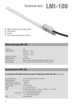
Technical data Open miniature measuring system Contactless Sturdy Any measuring length up to 30 m Measuring tape LMB-100 Grating pitch: Linearity deviation: Coefficient of expansion: Measuring length: Mechanical version: Reference position: ~11 ppm maximum 30 m Stainless steel measuring tape with adhesive coating for mounting Centre as standard, any position and number or distance-coded Scanning head LMK-100 in connection with external electronic signal conditioning module SKE only (see Page 12) Operating temperature: Storage temperature: Shock resistance (11 ms): Vibration resistance...
Open the catalog to page 6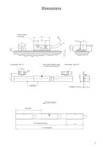
Ground surface (both sides) End position switching point = centre of scanning head Count direction ML Measuring length GL Total length
Open the catalog to page 7
Technical data Guided, encapsulated miniature measuring system Sturdy design High accuracy Simple, cost-saving assembly Large mounting tolerances Stainless steel Measuring rail LMF-200 Grating pitch: Graduation accuracy: Coefficient of expansion: ~11 ppm Measuring length in mm - one-piece: 170 / 220 / 270 / 320 / 420 / 520 / 620 / 720 / 820 / 920 / 1020 Greater lengths on request Reference position: Centre as standard, any position and number or distance-coded Measuring slider LMK-200 in connection with external electronic signal conditioning module SKE only (see Page 12) Traverse speed:...
Open the catalog to page 8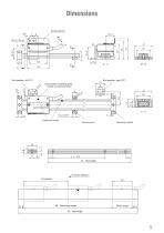
Dimensions Spring element End position, right ("R") End position switching point = centre of scanning head Reference marks Mounting foot Mounting bracket Count direction RI-position Slider length
Open the catalog to page 9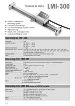
Technical data Guided, encapsulated measuring system Extremely robust design Any measured length can be realized High accuracy Simple, cost-saving assembly Large mounting tolerances Measuring rail LMF-300 Grating pitch: Graduation accuracy: Reference position: Option Any measured length in multi-part version Centre as standard, any position and number or distance-coded Corrosion protection (ZnFe coating) Measuring slider LMK-301 Output signal: Traverse speed: Operating temperature: Storage temperature: Shock resistance (11 ms): Vibration resistance (55-2000 Hz): Protection class: Supply:...
Open the catalog to page 10
Spring element End position switching point = centre of scanning head Reference marks Mounting foot Slider length
Open the catalog to page 11
Technical data Input - measuring system Input - measuring system Signal conditioning SKE-G1 (For measuring system LMI-100 and LMI-200) Output signal: Traverse speed: Operating temperature: Storage temperature: Protection class: 1 Vpp/1000/jm referred to terminating resistor 120 Q (see circuit and signal diagram) 5 V ±5% at device, 250 mA incl. measuring slider Signal conditioning SKE-D2 same as SKE-D1, except Output signal: TTL in accordance with RS 422 A (see circuit and signal diagram) Traverse speed: SKE-Q2-0 (resolution 1 Qum) 10 m/s Supply 5 V ±5% at device, max. 350 mA incl. measuring...
Open the catalog to page 12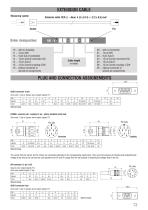
EXTENSION CABLE Measuring system Extension cable Order designation: 10 ... with no Coupling 11 ... 12 pin DIN 13 ... 9 pin Sub-D (standard) 14 ... 12 pin Connei connector CW 15 ... 15 pin Sub-D 16 ... 12 pin Connei coupling CCW 19 ... Special connector or special pin assignments 00 ... with no Connector 01 ... 12 pin DIN 03 ... 9 pin Sub-D 04 ... 12 pin Connei connectot CW 05 ... 15 pin Sub-D 06 ... 12 pin Connei coupling CCW 09 ... Special connector or special pin assignments Cable length in metre PLUG AND CONNECTION ASSIGNEMENTS 39,2 Sine-wave 1 Vpp or Square-wave output signals TTL PIN...
Open the catalog to page 13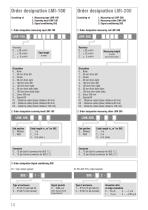
1. Measuring tape LMB-100 2. Scanning head LMK-100 3. Signal conditioning SKE 1. Order designation measuring tape LMB-100 1. Order designation measuring rail LMF-200 RI-position 0 ... None 1 ... 50 mm from left 2 ... Centre 3 ... 50 mm from right 4 ... 100 mm from left 5 ... 100 mm from right 6 ... 50 mm from both sides 7 ... 100 mm from both sides 8 ... Every 100 mm 9 ... Special-RI K1 ... Distance-coded (basic distance 40 mm) K2 ... Distance-coded (basic distance 80 mm) K3 ... Distance-coded (basic distance 120 mm) 2. Order designation scanning head LMK-100 End position 0 ... Without 1...
Open the catalog to page 14All VELMEX catalogs and technical brochures
-
UNISLIDE® TA SYSTEM LAYOUT
1 Pages
-
Limit Switches
7 Pages
-
Rotary-incremental-encoder
3 Pages
-
Velmex Catalog
149 Pages
-
Linear and Rotary Encoders
5 Pages
-
XSlide Spec Overview
8 Pages
-
VRO™ Digital Readout Spec Sheet
10 Pages
-
Rotary-Encoder-Lead-Screw
12 Pages
-
Magnetic_Encoder
1 Pages
-
PK296B2A-SG36,_StepperMotor
3 Pages
-
PK296B2A-SG18,_StepperMotor
3 Pages
-
PK296B2A-SG10,_StepperMotor
3 Pages
-
PK264-03A,_StepperMotor
2 Pages
-
PK243A1A-SG18,_StepperMotor
2 Pages
-
Lead Screw Translation
6 Pages
-
VXM Full Command Summary
3 Pages
-
VXM Controller
8 Pages
-
UniSlide
16 Pages
-
TA System 7-1-14 Rev C
4 Pages
-
BiSlide Side Knob
2 Pages
-
BISlide Catolog
16 Pages
Archived catalogs
-
VRO Overview
5 Pages


