 Website:
VELMEX, Inc.
Group: Velmex
Catalog excerpts

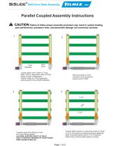
BISLIDE® Belt Drive Slide Assembly Parallel Coupled Assembly Instructions ! CAUTION Failure to follow proper assembly procedure may result in system binding, poor performance, premature wear, and permanent damage not covered by warranty T-slot Separator Inner Cleat Loosely attach Inner Cleats to T-nuts, Slide T-Nuts in Separators used for Outer Cleats to ends of Separators, Position Slides on T-Slot Separators wide enough for Drive Shaft installation With Drive Shaft in Cover compress Cover slip-joint to expose ends of Shaft Carefully insert Drive Shaft on Hubs and move Slides together CAUTION: SUPPORT SHAFT AT EACH END TO PREVENT BENDING OF SHAFT/HUBS, KEEP SLIDES PARALLEL Finalize Slide position by measuring Center to Center (C to C) and square by measuring (equal) diagonals, Refer To packing slip/invoice for C to C distance, Attach Outer Cleats & lightly tighten all cleats
Open the catalog to page 1
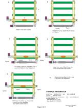
Tighten Attach Y Axis with 4 Cleats With 3/16” hex key tighten Shaft Clamps to 170 lb-in Fully tighten Cleats on Separator under Y, Loosen all Cleats on other Separators Attach Each end of Shaft Cover with 1/4-20 Socket Head Cap screws Repeat previous Step 9 until X Axis is secured to all Separators CONTACT INFORMATION By Phone: 585-657-6151 and By Fax: 585-657-6153 On the Internet:www.velmex.com By mail: Velmex, Inc. 7550 State Route 5 & 20 Bloomfield, NY 14469USA With Motor Controller Jog X Axis Until Y Axis is over next Separator and Tighten Cleats under Y
Open the catalog to page 2All VELMEX catalogs and technical brochures
-
UNISLIDE® TA SYSTEM LAYOUT
1 Pages
-
Limit Switches
7 Pages
-
Rotary-incremental-encoder
3 Pages
-
Velmex Catalog
149 Pages
-
Linear and Rotary Encoders
5 Pages
-
XSlide Spec Overview
8 Pages
-
VRO™ Digital Readout Spec Sheet
10 Pages
-
Rotary-Encoder-Lead-Screw
12 Pages
-
Magnetic_Encoder
1 Pages
-
Inductive_LinearTapeEncoders
15 Pages
-
PK296B2A-SG36,_StepperMotor
3 Pages
-
PK296B2A-SG18,_StepperMotor
3 Pages
-
PK296B2A-SG10,_StepperMotor
3 Pages
-
PK264-03A,_StepperMotor
2 Pages
-
PK243A1A-SG18,_StepperMotor
2 Pages
-
Lead Screw Translation
6 Pages
-
VXM Full Command Summary
3 Pages
-
VXM Controller
8 Pages
-
UniSlide
16 Pages
-
TA System 7-1-14 Rev C
4 Pages
-
BiSlide Side Knob
2 Pages
-
BISlide Catolog
16 Pages
Archived catalogs
-
VRO Overview
5 Pages


