

VT67EC

VT67EC
Overview
This document provides detailed technical specifications, operating characteristics, and installation guidelines for the VT67EC series high-performance vane pumps. It includes data on volumetric displacement, noise levels, internal leakage, hydromechanical power loss, permissible loads, mounting options, and shaft types.
1. Volumetric Displacement
The pumps have various volumetric displacements ranging from 10.8 cm³/rev (0.66 in³/rev) to 268.7 cm³/rev (16.40 in³/rev). Specific models include designations such as 005, 006, 008, 010, 012, 014, 015, 020, 022, 025, 028, 031, 042, 045, 050, 052, 054, 057, 062, 066, 072, 085, and their corresponding displacement values.
2. Noise Level
Noise levels are measured in dB(A) at 1 meter distance according to ISO 4412 standards. Noise data is provided for different speeds (1200, 1800, 2200 rpm) and viscosities (notably 24 cSt). The noise level for double pumps is given with each section discharging at specified pressures. The noise level formula is Lw = Lp + 8 dB(A).
3. Internal Leakage
Internal leakage values are typical and expressed in liters per minute (lpm) or gallons per minute (gpm). The document warns against operating the pump for more than 5 seconds at any speed or viscosity if internal leakage exceeds 50% of the theoretical flow. Total leakage is the sum of losses from each section under operating conditions.
4. Hydromechanical Power Loss
Power loss data is provided in kilowatts (kW) for individual cartridges at various operating pressures and speeds. Total hydromechanical power loss is the sum of losses from each section. The document includes curves and tables showing power loss versus pressure and speed.
5. Permissible Loads
The maximum permissible axial load (Fa) on the pump shaft is 2000 N (449 lbs). Radial load limits are also indicated for different pump sizes and configurations.
6. Mounting and Shaft Types
Mounting options include SAE C 2-bolt flanges (J744c) and 4-bolt SAE flanges (J518). Seal classes are specified for mineral oil and fire-resistant fluids (S1, S4, S5). The direction of rotation can be clockwise (R) or counter-clockwise (L).
Shaft types include:
- Keyed SAE CC (Code 1)
- Keyed non-SAE (Code 2)
- SAE C splined shaft (Code 3)
- SAE CC splined shaft (Code 4)
Mounting torque values are provided for different shaft types, e.g., 59 ft.lbs (80 Nm) for keyed shafts and 138 ft.lbs for splined shafts.
7. Operating Conditions and Limitations
- Maximum internal pressure varies by model, e.g., 90 bar (1300 psi) max internal for model 085, 240 bar max for others.
- Maximum rotational speeds vary: 2000 RPM max for model 085, 2500 RPM max for models 025, 028, 031.
- Viscosity recommendations include 24 cSt typical, with warnings against operation at viscosities or speeds causing excessive leakage.
- Input power and flow rates are tabulated for pressures of 140 bar (2000 psi), 240 bar (3500 psi), and 275 bar (4000 psi) at 1800 rpm.
8. Additional Notes and Recommendations
- Do not operate the pump for more than 5 seconds if internal leakage exceeds 50% of theoretical flow.
- Total leakage and power loss should be calculated as the sum of individual section losses under actual operating conditions.
- Porting combinations and design letters are customizable per application requirements.
Summary Tables and Data
The document contains extensive tabulated data correlating volumetric displacement, flow rates, pressure ratings, power losses, noise levels, and mounting dimensions. Key parameters such as shaft torque limits, mounting torque, and thread specifications are also detailed.
Critical Parameters
- Max axial load: 2000 N (449 lbs)
- Max internal pressure varies by model (up to 275 bar)
- Max speed varies by model (up to 2500 RPM)
- Noise levels measured per ISO 4412
- Seal classes adapted for fluid types
- Mounting flanges: SAE C 2-bolt and 4-bolt options
Conclusion
This technical document serves as a comprehensive reference for selecting, installing, and operating VT67EC series vane pumps. It emphasizes adherence to pressure, speed, and leakage limits to ensure optimal performance and longevity. Proper mounting, shaft selection, and fluid compatibility are critical for reliable operation.
Catalog excerpts
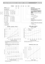
HIGH PERFORMANCE VANE PUMP VT67EC Mounting W/connection variables INTERNAL LEAKAGE ( TYPICAL ) Seal class 4 - S4 (for fire resistant fluids) resistant fluids) Design letter Porting combination (see page BM-1-5) Direction of rotation (view on shaft end) NOISE LEVEL ( TYPICAL) Do not operate pump more than 5 seconds at any speed or viscosity if internal leakage is more than 50 of theoretical flow. Total leakage is the sum of each section loss at its operating Double pump noise level is given with each section discharging at the pressure noted on the curve. HYDROMECHANICAL POWER LOSS (TYPICAL) Total hydromechanical power loss is the sum of each section PERMISSIBLE RADIAL LOAD Maximum permissible axial load Fa = 2000 N (449 Lbs)
Open the catalog to page 1All Veljan Hydrair Limited catalogs and technical brochures
 Hydraulic Filters
46 Pages
 VT7QDCC
3 Pages
 VR5V06 Series
8 Pages
 VR5U08 Series
8 Pages
 VR4R series
8 Pages
 E Series
7 Pages
 Gear Pump - D Series
7 Pages
 Hydraulic Filters Catalogue
46 Pages
 Gear Pump - C Series
7 Pages
 Gear Pump - B Series
6 Pages
 V4DO1
V4DO113 Pages
 V4DO2
V4DO214 Pages
 V4DO6
V4DO616 Pages
 VR4V
VR4V8 Pages
 VT7QDCB
3 Pages
 VT6CC
VT6CC2 Pages
 VT7DSW
2 Pages
 VTXB
VTXB3 Pages
 VJ
VJ13 Pages
 VCC
VCC6 Pages
 VSD
VSD6 Pages
 VIC
VIC7 Pages
 ILV 750
7 Pages
 ILV 725
7 Pages
 ILV 720
9 Pages
 ILV 714
9 Pages
 Hydraulic Cylinders
23 Pages
 VVV01
VVV012 Pages
 System Saver - Single Vane Pump
17 Pages
 VT67EDC
3 Pages
 VT67DDCS
3 Pages
 VT67DCC
3 Pages
 VT67BB
2 Pages
 VT6CB
VT6CB3 Pages
 VT6BB
VT6BB4 Pages
 VTXBB
VTXBB4 Pages
 VD4S06
14 Pages
 VD4S03
12 Pages
 VDRV7 - VDV7 06 ? 08
6 Pages
 VR5S06
8 Pages
 VR4S03
8 Pages
 VR4U10
9 Pages
 VR5V12
8 Pages
 VRIEO2
5 Pages
 VT7EE/VT7EES
2 Pages
 VT6EDCR
3 Pages
 VT6DCCR
3 Pages
 VT6CRM
2 Pages
 VT6CR
VT6CR2 Pages
 J9V045
15 Pages
 J9V009
7 Pages
 VM4E
VM4E2 Pages
 VM4D
VM4D2 Pages
 VM4C
VM4C2 Pages
 VM3B
VM3B2 Pages
 System Saver
17 Pages


Archived catalogs
 VELJAN HYDRAULIC PRODUCTS
11 Pages
- Valve
- Cylinder
- Regulating valve
- Flange valve
- Liquid filter
- Flap valve
- Check valve
- Directional control valve
- Hydraulic pump
- Double-acting cylinder
- Filter with cartridge
- Hydraulic cylinder
- Hydraulic valve
- Hydraulic directional control valve
- Spool hydraulic directional control valve
- Relief valve
- Compact cylinder
- Hydraulic filter
- In-line filter
- Ball check valve