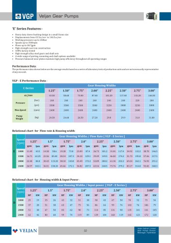
Catalog excerpts
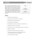
VEUAN model V4D06 pilot operated Directional Control valves conform to NFPA D08, CETOP 08 standard interface. These are subplate and manifold mounted and can be used in conjunction with stack valve system. The valve mounting interface and electrical connection methods conform to international standards CETOP.ISO, DIN. The coils used in the wet pin design solenoids are available in A.C. and D.C. voltages and are continuously rated. Precise guide for all types of spools is achieved by uniquely designed eight annuli body. Spools are interchangeable and no selective assembly is necessary. Streamlined internal channels ensure minimum pressure drop at maximum flow. ♦ Extremely low pressure drop-energy saving. ♦ High functional limit up to 185 gpm(700l/min) at nominal pressure. ♦ Mounting configuration according to CETOP, ISO 4401. ♦ Nominal operating pressure 350bar (5000psi). ♦ Interchangeability of spools & bodies due to high precision manufacturing processes. ♦ Actuated by electrical / hydraulic or lever mechanism. ♦ Wide range of A.C. and D.C. coil voltages are available both with or without manual override. ♦ Wide variety of spools available. ♦ Change of solenoid coil is fast and simple without risk of oil leakage. ♦ Permissible pressure in the tank port up to 350bar (5000psi) with external drain, up to 210 bar (3000psi) with internal drain (see characteristics). ♦ Every valve is factory tested prior to despatch.
Open the catalog to page 1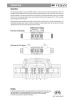
The electrically operated 4-way valve V4D06 consists of a main body and a solenoid operated pilot valve. The energized solenoid shifts the pilot control spool, thus directing fluid to one end of the main spool, and moving it to the desired position. Fluid can then flow from port P to either port A or B whilst the alternate port (B or A) is connected to the tank line. The necessary pilot pressure can be obtained internally from the system port P or from an external pressure supply connected to portX. De-energizing the solenoid allows both the pilot control and the main spool to return to...
Open the catalog to page 2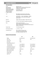
Mounting Position Ambient temperature range Operating Pressure(P,A,B,X) Operating Pressure(T,Y) External pilot pressure Viscosity range Fluid temperature range Contamination level Sliding spool valve Subplate conform to NFPA D08, CETOP 08, ISO 4401. Optional (Horizontal recommended) 9bar (130psi) for spools with open center position 10 bar(145psi) for spools with closed center position. a pilot orifice dia. 1,0 mm in P-port is recommended 185gpm (700l/min) (see diagram - Pressure drop curves) Petroleum base anti-wear fluids. Such as mineral oil according to DIN 51524/25. Maximum catalogue...
Open the catalog to page 3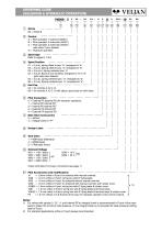
ORDERING CODE (SOLENOID & HYDRAULIC OPERATION) A = Pilot operated, 1 solenoid (V4D01) B = Pilot operated, 2 solenoids (V4D01) C = Pilot operated, 2 solenoids (V4D01) pilot valve; 2 pos. detents 01 = 2 (a,b), spring offset to pos. "b", energized to "a" 02 = 2 (a,b), Spring offset to pos. "a", energized to "b". 04 = 2 (a,b), Spool is not centered, energized to "a" or "b" (pilot valve with detents). 05 = 2 (o,b), spring centered pos. "o", energized to "b". 06 = 2 (o,a), Spring centered pos. "o", energized to "a". 09 = for controls A, B, C, O with adjust, spool stop on both sides. 0 = External...
Open the catalog to page 4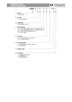
ORDERING CODE (LEVER OPERATION) 01 = 2 (a,b), Spring offset to pos. "b", activated to pos. "a". 02 = 2 (a,b), Spring offset to pos. "a", activated to pos. "b".
Open the catalog to page 5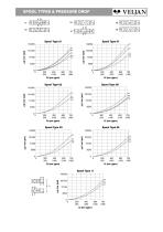
SPOOL TYPES & PRESSURE DROP
Open the catalog to page 6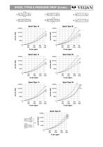
SPOOL TYPES & PRESSURE DROP (Contd.) L*AT| Bl iTSlM
Open the catalog to page 7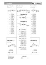
Spring Centering Spring Offset Spring Centering Pilot valve with Detents Spring Centering Spring Offset @ Lever operation
Open the catalog to page 8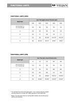
FUNCTIONAL LIMITS The "fail safe" flow limits of the spool types 11 & 51 must be reduced at higher operating pressure to comply with "safety regulations" where applicable. Means: The main spool returns to "spring offset" position only by spring force (without pilot pressure).
Open the catalog to page 9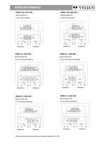
DETAILED SYMBOLS X-external Y-external X-external Y-external X-external Y-external 2 (a,b), Pilot Valve with detents X-external Y-external X-external Y-external X-external Y-external 1) Plug mounted according to desired internal or external PP or PD.
Open the catalog to page 10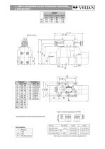
1- AND 2-SOLENOID AC/DC OPERATED VERSIONS, Note: Plug-in connectors to be ordered as separate items.
Open the catalog to page 11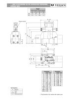
1- AND 2-SOLENOID AC/DC OPERATED VERSIONS, * This dimension is for version with rubber cover
Open the catalog to page 12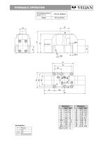
HYDRAULIC OPERATION
Open the catalog to page 13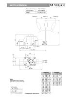
LEVER OPERATION
Open the catalog to page 14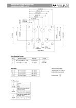
MOUNTING CONFIGURATION Valve Mounting Screws
Open the catalog to page 15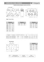
SUBPLATES, PANEL OPENING Subplate (mounting configuration conforms to ISO 4401)
Open the catalog to page 16All Veljan Hydrair Limited catalogs and technical brochures
-
Hydraulic Filters
46 Pages
-
VT7QDCC
3 Pages
-
VR5V06 Series
8 Pages
-
VR5U08 Series
8 Pages
-
VR4R series
8 Pages
-
E Series
7 Pages
-
Gear Pump - D Series
7 Pages
-
Hydraulic Filters Catalogue
46 Pages
-
Gear Pump - C Series
7 Pages
-
Gear Pump - B Series
6 Pages
-
V4DO1
13 Pages
-
V4DO2
14 Pages
-
VR4V
8 Pages
-
VT7QDCB
3 Pages
-
VT6CC
2 Pages
-
VT7DSW
2 Pages
-
VTXB
3 Pages
-
VJ
13 Pages
-
VCC
6 Pages
-
VSD
6 Pages
-
VIC
7 Pages
-
ILV 750
7 Pages
-
ILV 725
7 Pages
-
ILV 720
9 Pages
-
ILV 714
9 Pages
-
Hydraulic Cylinders
23 Pages
-
VVV01
2 Pages
-
System Saver - Single Vane Pump
17 Pages
-
VT67EDC
3 Pages
-
VT67DDCS
3 Pages
-
VT67DCC
3 Pages
-
VT67EC
2 Pages
-
VT67BB
2 Pages
-
VT6CB
3 Pages
-
VT6BB
4 Pages
-
VTXBB
4 Pages
-
VD4S06
14 Pages
-
VD4S03
12 Pages
-
VDRV7 - VDV7 06 ? 08
6 Pages
-
VR5S06
8 Pages
-
VR4S03
8 Pages
-
VR4U10
9 Pages
-
VR5V12
8 Pages
-
VRIEO2
5 Pages
-
VT7EE/VT7EES
2 Pages
-
VT6EDCR
3 Pages
-
VT6DCCR
3 Pages
-
VT6CRM
2 Pages
-
VT6CR
2 Pages
-
J9V045
15 Pages
-
J9V009
7 Pages
-
VM4E
2 Pages
-
VM4D
2 Pages
-
VM4C
2 Pages
-
VM3B
2 Pages
-
System Saver
17 Pages
Archived catalogs
-
VELJAN HYDRAULIC PRODUCTS
11 Pages


