- Catalogs
- Veljan Hydrair Limited
- V20 Mobile Directional Control Valve Catalogue
V20 Mobile Directional Control Valve Catalogue
1 /18Pages

V20 Mobile Directional Control Valve Catalogue
1 /18Pages
Catalog excerpts

Mobile Directional Control Valves We Help You See Your Ideas Work
Open the catalog to page 1
Mobile Directional Control Valves - V20 Introduction: VELJAN V20M Mobile directional control valve is a segment type design that can be stacked together in parallel. It basically consists of three elements-an inlet Section, a work section with a wide choice of spool configurations and an outlet section, all bolted together as a single unit. The number of work sections in the valve unit are decided upon by the number of hydraulic elements to be operated. The valves are mounted on equipment at one location to meet the requirements of controlling multiple hydraulic elements from a single point by...
Open the catalog to page 2
Work section Design Letter Seal Class 1- Buna N 5 - Viton Ports Connections S - SAE thread G - BSP thread N - NPTF thread Handle Position 1 - Lever in UPWARDS 2 - Lever in DOWNWARDS 3 - Lever With JOY STICK Control Outlet Blocking Code 1-Top Outlet Port 2-Side Outlet Port 3-Top Outlet With Power Beyond 4-Outlet With Closed Center 0 - NONE 1 - WRV ON PORT 'A'. 2 - WRV ON PORT 'B'. 3 - WRV ON PORT 'A & B'. 4 - ACV ON PORT 'A'. 5 - ACV ON PORT 'B'. 6 - ACV ON PORT 'A & B'. ACV- ANTICAVITATION VALVE Auxiliary Valves WRV Pressure Setting (bar) (ONLY FOR WORKPORT RELIEF VALVE) Outlet section WRV- WORK...
Open the catalog to page 3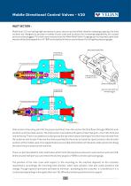
Mobile Directional Control Valves - V20 INLET SECTION : Made from S.G Iron having high resistance to wear, seizure and excellent vibration damping capacity, the inlet sections are designed to provide a variety of port sizes and locations for increasing adaptability. All unused ports must be plugged. This Inlet cover has provision for Main Relief Valve. If a gauge port is required a port hole may be drilled and tapped for a ¼" BSP and installed in the unused inlet port for fixing the pressure gauge. Main Pressure Relief Valve Top Inlet Port (P) or Gauge Port (G) Direct Opearated Main Relief Valve...
Open the catalog to page 4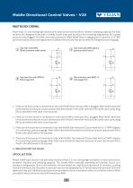
Mobile Directional Control Valves - V20 INLET BLOCK CODING: Made from S.G Iron having high resistance to wear,seizure and excellent vibration damping capacity, the inlet sections are designed to provide a variety of port sizes and locations for increasing adaptability. All unused ports must be plugged. This Inlet cover has provision for Main Relief Valve. If a gauge port is required a 3/4" BSP port hole may be drilled and tapped and installed at the unused inlet pot location for fixing the pressure gauge. Top Inlet with DPRV (Direct pressure relief valve) Side inlet with DPRV (Direct pressure...
Open the catalog to page 5
Mobile Directional Control Valves - V20 Load check valve SECTIONAL DRAWING Port (B) Port For Auxilary valve (Anticavitation valve (ACV), Work port relief valve (WRV) Port For Auxilary valve (Anticavitation valve(ACV), Work port relief valve(WRV))
Open the catalog to page 6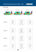
Mobile Directional Control Valves - V20 SPOOL TYPES: Left Stroke Neutral Position Right Stroke
Open the catalog to page 7
Mobile Directional Control Valves - V20 SPOOL POSITIONS: 1. SPRING CENTERED Spool Section (Body) Guide Ring Spring Support Spring Screw Spool Forward position Centre position Backword position Spool is assembled on one side with lever assembly and on the other side with spring and spring supports housed in an end cap. At the neutral condition lever position is 90° and it moves 15° either side from center for forward and back word positions. Linearly the spool will move 7.1 mm on either side from the center position. The spring force bring the lever to the neutral position when released from either...
Open the catalog to page 8
Mobile Directional Control Valves - V20 Lever centre position Grip-lever Bellow Dowel Pin End Cap - Bellow SPOOL SECTION (BODY) Auxilary Valves: Work Port Relief Valve WORKPORT RELIEF VALVE (WRV): These are used for setting maximum pressure limit in ports A and / or B in individual work sections in addition to the common main relief valve installed in the inlet section.. HOW TO SET PRESSURE ONWORK PORT RELIEF: A good pressure gage must be installed in the line which is in communication with the work port relief. A load must be applied in a manner to reach the set pressure of the port relief unit....
Open the catalog to page 9
Mobile Directional Control Valves - V20 SPOOL SECTION WITH ACV AND WRV :Work Port Relief Valve Load Check Valve Anticavitation Valve (AV) Handle Position: 1. Upwards: Lever Will Be Fitted Vertically Upwards With Spool Section Ports. 2. Downwards: Lever Will Be Fitted Vertically Downwards With Spool Section Ports. 3 - Lever With JOY STICK Control Outlet Section: Made from S.G Iron having high resistance to wear, seizure and excellent vibration damping capacity, the Outlet sections are designed to provide a variety of Port sizes and locations for increasing adaptability. It has outlet ports on...
Open the catalog to page 10
Mobile Directional Control Valves - V20 The tank connections from the work port-A comes through the work sections and up to the outlet body,in the outlet section it gets connected to the conversion port. The tank connections from the B-ports of the spool sections gets connected to the end outlet port. The end outlet port is connected to the conversion port, top port of the outlet body and to the outlet port of the inlet body. These inter connection makes it possible for the pressure oil from the inlet section port to reach the outlet section conversion port and further allows it to come back...
Open the catalog to page 11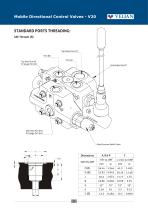
Mobile Directional Control Valves - V20 STANDARD PORTS THREADING: SAE Threads (S): Top Outlet Port (T) Port (B) Port (A) Top Inlet Port (P) Or Gauge Port (G) Side Inlet Port (PL) Or Gauge Port (GL) Main Pressure Relief Valve
Open the catalog to page 12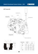
Mobile Directional Control Valves - V20 Port (A) Top Inlet Port (P) Or Gauge Port (G) Port (B) End Outlet Port (T) Side Inlet Port (PL) or Gauge Port (GL) Main Pressure Relief Valve
Open the catalog to page 13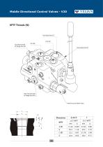
Mobile Directional Control Valves - V20 Port (A) Top Inlet Port (P) Or Gauge Port (G) Port (B) End Outlet Port (T) Side Inlet Port (PL) or Gauge Port (GL) Main Pressure Relief Valve Dimensions NPTF
Open the catalog to page 14
Mobile Directional Control Valves - V20 PERFORMANCE DATA (PRESSURE DROP VS FLOW): Open Center Pressure Drop: Typical pressure drop 1to 12 section valve assemblies using inlet to outlet (Pressuredrop "P" to "T") Inlet To Work Port Pressure Drop: Typical Pressure Drop 1 To 12 Section Valve Assemblies Using Inlet To Work Port A & B (pressure Drop "p" To "a/b").
Open the catalog to page 15All Veljan Hydrair Limited catalogs and technical brochures
 Hydraulic Filters
46 Pages
 VT7QDCC
3 Pages
 VR5V06 Series
8 Pages
 VR5U08 Series
8 Pages
 VR4R series
8 Pages
 E Series
7 Pages
 Gear Pump - D Series
7 Pages
 Hydraulic Filters Catalogue
46 Pages
 Gear Pump - C Series
7 Pages
 Gear Pump - B Series
6 Pages
 V4DO1
V4DO113 Pages
 V4DO2
V4DO214 Pages
 V4DO6
V4DO616 Pages
 VR4V
VR4V8 Pages
 VT7QDCB
3 Pages
 VT6CC
VT6CC2 Pages
 VT7DSW
2 Pages
 VTXB
VTXB3 Pages
 VJ
VJ13 Pages
 VCC
VCC6 Pages
 VSD
VSD6 Pages
 VIC
VIC7 Pages
 ILV 750
7 Pages
 ILV 725
7 Pages
 ILV 720
9 Pages
 ILV 714
9 Pages
 Hydraulic Cylinders
23 Pages
 VVV01
VVV012 Pages
 System Saver - Single Vane Pump
17 Pages
 VT67EDC
3 Pages
 VT67DDCS
3 Pages
 VT67DCC
3 Pages
 VT67EC
2 Pages
 VT67BB
2 Pages
 VT6CB
VT6CB3 Pages
 VT6BB
VT6BB4 Pages
 VTXBB
VTXBB4 Pages
 VD4S06
14 Pages
 VD4S03
12 Pages
 VDRV7 - VDV7 06 ? 08
6 Pages
 VR5S06
8 Pages
 VR4S03
8 Pages
 VR4U10
9 Pages
 VR5V12
8 Pages
 VRIEO2
5 Pages
 VT7EE/VT7EES
2 Pages
 VT6EDCR
3 Pages
 VT6DCCR
3 Pages
 VT6CRM
2 Pages
 VT6CR
VT6CR2 Pages
 J9V045
15 Pages
 J9V009
7 Pages
 VM4E
VM4E2 Pages
 VM4D
VM4D2 Pages
 VM4C
VM4C2 Pages
 VM3B
VM3B2 Pages
 System Saver
17 Pages


Archived catalogs
 VELJAN HYDRAULIC PRODUCTS
11 Pages