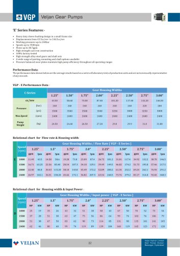
Catalog excerpts

SYSTEM SAVER SYSTEM SAVER CONCEPT Utilizes standard catalogued hydraulic components. Assembly of a complete system on the pump, without pipe or manifold block with bolt on valves.The evident saving of space and cost is completed in addition by a best response of relief and unloading valves,due to the very small oil volume compressed between valves and pumps. ► Overall cost reduction ► Pre-assembled integrated functions Standard components in any package are pre-tested to their full performance specifications. REDUCED OVERALL INSTALLATION COSTS Easy specification of required sub system along with quick assembly and no charge for mounting hardware,combine to make the "System Saver" very cost-effective. DESIGN FLEXIBILITY Allows you to combine any selection of the pressure relief and unloading valves (with manual or electrical) with any combination of single, double & triple high performance vane pumps. SINGLE PUMP SYSTEM SAVER MODEL CODE Pump Model Code (For Model code & Installation dimensions please refer pages 7-10) UO - Unloader with Vent valve (normally open) UB - Unloader with Vent valve (normally closed) VO - Relief valve with Vent valve (normally open) VB - Relief valve with Vent valve (normally closed) (For Model code & Installation dimensions please refer pages 31 -37) 2 - NPTF threaded port 3 - Socket weld flange Check valve D - Unloading check valve Unloader with Check valve (NUD)
Open the catalog to page 1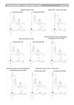
SYSTEM SAVER - SINGLE VANE PUMPS Unloader with Vent valve normally open (UO) i normally closed (UB) Relief valve + Check valve (NVC) Relief valve with vent valve Unloader with Vent valve (normally open) + Unloading check valve (UOD) Unloader with Vent valve (normally closed) + Unloading check valve (UBD) Relief valve with vent valve + Check valve normally open (VOC) normally closed (VBC)
Open the catalog to page 2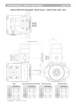
SYSTEM SAVER - SINGLE VANE PUMPS SINGLE PUMP WITH UNLOADER / RELIEF VALVE + CHECK VALVE (NUD - NVC) SOCKET HEAD CAP SCREWS
Open the catalog to page 4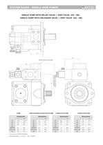
SYSTEM SAVER - SINGLE VANE PUMPS SINGLE PUMP WITH RELIEF VALVE + VENT VALVE (VO - VB) \ SINGLE PUMP WITH UNLOADER VALVE + VENT VALVE (UO - UB) SOCKET HEAD CAP SCREWS
Open the catalog to page 5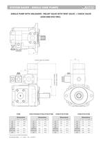
SYSTEM SAVER - SINGLE VANE PUMPS SINGLE PUMP WITH UNLOADER / RELIEF VALVE WITH VENT VALVE + CHECK VALVE
Open the catalog to page 6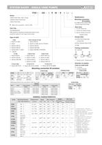
SYSTEM SAVER - SINGLE VANE PUMPS Y- Metric port connection, Omit for UNC Refer general & operating characteristics table of vane pumps for options of cam rings of each series Mounting connection W/variables - Mounting connection - Seal class 4 - S4 (for fire resistant fluids) resistant fluids) - Design letter - Porting combination S - Suction port P - Pressure port Shaft torque limits ¡n3/rev x psl (ml/rev x bar) Vp x p max. GENERAL CHARACTERISTICS
Open the catalog to page 7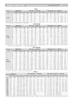
SINGLE VANE PUMP - Operating Characteristics - Not to use because internal leakage greater than 50%theoretical flow. 1) 025-028-031 = 2500 R.RM. max. 2) 022= 275 bar max. int, 3) 025 = 240 bar max. int, 4) 028-031 = 210 bar max. int. - Not to use because internal leakage greater than 50%of theoretical flow.
Open the catalog to page 8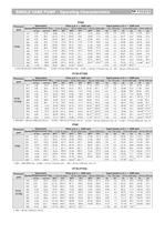
SINGLE VANE PUMP - Operating Characteristics
Open the catalog to page 9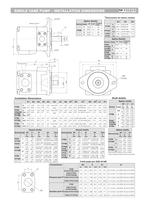
SINGLE VANE PUMP - INSTALLATION DIMENSIONS Dimensions for below models Installation Dimensions Shaft details Note: All spline shafts are Flat root side fit
Open the catalog to page 10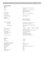
PILOT OPERATED PRESSURE CONTROLS FALNGED TYPE VR5 SERIES QQMESSl Mounting position Port sizes (nominal) Ambient temperature Special working conditions Pressure control range Pilot operated Relief /Unloading/Sequence Valve Poppet type Consult VELJAN Minimum - depends on flow Maximum operating pressure PortYYI (pilot drain) Fluid temperature range Viscosity Range Optimum operating viscosity Seal compatibility Cleanliness recommended depends on pump delivery Mineral oil as per DIN 51524/25 or other fluids on request Code 1 (Buna N) or Code 5 (Viton) (contact Veljan with specific oil details)...
Open the catalog to page 11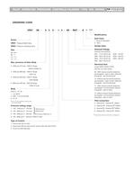
PILOT OPERATED PRESSURE CONTROLS FALNGED TYPE VR5 SERIES QQMESSl ORDERING CODE VR5V - Pressure Relief Valve VR5U - Pressure Unloading Valve Max. pressure of Valve Body ^) Port Y1 is only available at external drain from the pilot head Pressure setting range 2 - Hand knob (50 mm dia) (not for version with vent valve W01) 3 - Acron nut with lead seal Seal Class Design letter Solenoid Voltage (Omit for vent version) Electrical Vent Omit for non vent version 09 - With manual override (Solenoid de-energized : open to tank, Solenoid Energized : vent line blocked) 10 - Without manual override...
Open the catalog to page 12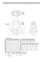
PILOT OPERATED PRESSURE CONTROLS FALNGED TYPE VR5 SERIES QQMESSl Installation Dimensions ' 1 ). CLOSED WHEN SUPPLIED
Open the catalog to page 13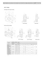
PILOT OPERATED PRESSURE CONTROLS FALNGED TYPE VR5 SERIES QQMESSl Inlet flange (only for pipe mounting) B.S.P.P Flange Socket weld Outlet and tank port flange N.P.T.F flange B.S.P.P flange Socket weld
Open the catalog to page 14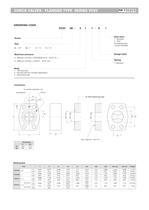
CHECK VALVES - FLANGED TYPE SERIES VC5V ORDERING CODE Maximum pressure 1 - with face seal, 2 - with face seal (for unloader application), 3 - without face seal Seal class consult VELJAN) Design letter for unloader application only for VC5V without face seal
Open the catalog to page 15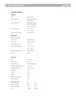
Mounting position Port sizes (nominal) Ambient temperature Special working conditions Pressure control range -PortX (pilot) Fluid Temperature Range Optimum operating viscosity Pilot Valve series VR4, Nominal voltage Permissible voltage fluctuation Input power Relative operating period Response time Solenoid energized Solenoid de-energized Refer to Ordering Code
Open the catalog to page 16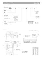
ORDERING CODE Spool position 1-Normal position: free flow from Z to Y Switch position: free flow from Z to Y 1 - plug - in - type solenoid with manual over-ride 2 - plug - in - type solenoid without manual over-ride Solenoid Voltage Seal Class Design letter Pilot valve over ride Vent valve plug-In connectors must be ordered separately. Solenoid coil can be positioned
Open the catalog to page 17All Veljan Hydrair Limited catalogs and technical brochures
-
Hydraulic Filters
46 Pages
-
VT7QDCC
3 Pages
-
VR5V06 Series
8 Pages
-
VR5U08 Series
8 Pages
-
VR4R series
8 Pages
-
E Series
7 Pages
-
Gear Pump - D Series
7 Pages
-
Hydraulic Filters Catalogue
46 Pages
-
Gear Pump - C Series
7 Pages
-
Gear Pump - B Series
6 Pages
-
V4DO1
13 Pages
-
V4DO2
14 Pages
-
V4DO6
16 Pages
-
VR4V
8 Pages
-
VT7QDCB
3 Pages
-
VT6CC
2 Pages
-
VT7DSW
2 Pages
-
VTXB
3 Pages
-
VJ
13 Pages
-
VCC
6 Pages
-
VSD
6 Pages
-
VIC
7 Pages
-
ILV 750
7 Pages
-
ILV 725
7 Pages
-
ILV 720
9 Pages
-
ILV 714
9 Pages
-
Hydraulic Cylinders
23 Pages
-
VVV01
2 Pages
-
System Saver - Single Vane Pump
17 Pages
-
VT67EDC
3 Pages
-
VT67DDCS
3 Pages
-
VT67DCC
3 Pages
-
VT67EC
2 Pages
-
VT67BB
2 Pages
-
VT6CB
3 Pages
-
VT6BB
4 Pages
-
VTXBB
4 Pages
-
VD4S06
14 Pages
-
VD4S03
12 Pages
-
VDRV7 - VDV7 06 ? 08
6 Pages
-
VR5S06
8 Pages
-
VR4S03
8 Pages
-
VR4U10
9 Pages
-
VR5V12
8 Pages
-
VRIEO2
5 Pages
-
VT7EE/VT7EES
2 Pages
-
VT6EDCR
3 Pages
-
VT6DCCR
3 Pages
-
VT6CRM
2 Pages
-
VT6CR
2 Pages
-
J9V045
15 Pages
-
J9V009
7 Pages
-
VM4E
2 Pages
-
VM4D
2 Pages
-
VM4C
2 Pages
-
VM3B
2 Pages
Archived catalogs
-
VELJAN HYDRAULIC PRODUCTS
11 Pages


