- Company
- Products
- Catalogs
- News & Trends
- Exhibitions
Radar
1 /16Pages

Radar
1 /16Pages
Catalog excerpts

Product information Radar Level measurement in liquids and bulk solids VEGAPULS C 11 VEGAPULS C 21 VEGAPULS C 22 VEGAPULS C 23 VEGAPULS 11 VEGAPULS 21 VEGAPULS 31
Open the catalog to page 1
Please note the Ex specific safety information that you can find at www.vega.com and that comes with each instrument. In hazardous areas you should take note of the appropriate regulations, conformity and type approval certificates of the sensors and power supply units. The sensors must only be operated on intrinsically safe circuits. The permissible electrical values are stated in the certificate. Take note of safety instructions for Ex appli
Open the catalog to page 2
Measuring principle 1 Measuring principle Measuring principle The devices emit a continuous radar signal through their antennas. The emitted signal is reflected by the medium and received as an echo by the antenna. The frequency difference between the emitted and received signal is proportional to the distance and depends on the filling height. The determined filling height is converted into a respective output signal and output as measured value. The 80 GHz technology used enables a unique focusing of the radar beam and a wide dynamic range of the radar sensors. The greater the dynamic range...
Open the catalog to page 3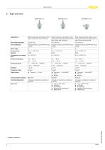
Type overview 2 Type overview VEGAPULS C 11 Water processing, pump stations, storm water overflow tank, level monitoring Water processing, pump stations, storm Water processing, pump stations, storm water overflow tank, flow measurement in water overflow tank, flow measurement in open flumes, level monitoring open flumes, level monitoring Integrated antenna system/PVDF encapsulated Integrated antenna system/PVDF encapsulated Integrated antenna system/PVDF encapsulated Beam angle Process fitting Connection for mounting strap Process temperature Process pressure Frequency range Signal output Communication...
Open the catalog to page 4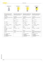
Type overview Water processing, pump stations, storm water overflow tank, flow measurement in open flumes, level monitoring Water treatment, storage tanks in all industrial areas, plastic tanks (measurement through the tank wall) Water treatment, storage tanks in all industrial areas, plastic tanks (measurement through the tank wall) Water treatment, storage tanks in all industrial areas, plastic tanks (measurement through the tank wall) Integrated antenna system/PVDF encapsulated Integrated antenna system/PVDF encapsulated Integrated antenna system/PVDF encapsulated Integrated antenna system/PVDF...
Open the catalog to page 5
Instrument selection 3 Instrument selection Application area The radar sensors of the VEGAPULS 10, 20, 30 series described here are used for non-contact level measurement of liquids and bulk solids. They can be used in both simple and aggressive liquids. The sensors also measure light and heavy bulk solids absolutely reliably, both with strong dust and noise generation and independent of buildup or condensation. Device overview VEGAPULS C 11 is the ideal sensor for non-contact level measurement in simple applications where a high degree of protection is required. It is particularly suitable for...
Open the catalog to page 6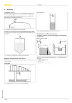
4 Mounting Installation position Mount the sensor in a position which is at least 200 mm (7.874 in) away from the vessel wall. If the sensor is installed in the center of dished or round vessel tops, multiple echoes can arise. However, these can be suppressed by an appropriate adjustment. Deep well level Fig. 6: Mounting of the radar sensor on round vessel tops In vessels with conical bottom it can be advantageous to mount the sensor in the centre of the vessel, as measurement is then possible down to the bottom. Fig. 9: Gauge measurement deep well, sensor mounting on lid Mounting examples flow...
Open the catalog to page 7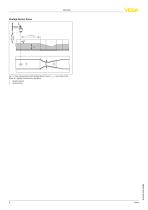
Khafagi-Venturi flume Fig. 11: Flow measurement with Khafagi-Venturi flume: hmax. = max. filling of the flume; B = tightest constriction in the flume 1 2 Position sensor Venturi flume
Open the catalog to page 8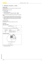
5 Electronics - Two-wire 4 … 20 mA Voltage supply Power the instrument via an energy-limited circuit (power max. 100 W) acc. to IEC 61010-1. Specifications of the voltage supply: Operating voltage –– 12 … 35 V DC • Permissible residual ripple –– for UN 12 V DC (12 V < UB < 18 V): ≤ 0,7 Veff (16 … 400 Hz) –– for UN 24 V DC (18 V < UB < 35 V): ≤ 1,0 Veff (16 … 400 Hz) Keep in mind the following additional factors that influence the operating voltage: Lower output voltage of the power supply unit under nominal load (e.g. with a sensor current of 20.5 mA or 22 mA in case of fault signal) Influence...
Open the catalog to page 9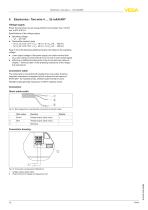
Electronics - Two-wire 4 … 20 mA/HART 6 Electronics - Two-wire 4 … 20 mA/HART Voltage supply Power the instrument via an energy-limited circuit (power max. 100 W) acc. to IEC 61010-1. Specifications of the voltage supply: Operating voltage –– 12 … 35 V DC • Permissible residual ripple –– for UN 12 V DC (12 V < UB < 18 V): ≤ 0,7 Veff (16 … 400 Hz) –– for UN 24 V DC (18 V < UB < 35 V): ≤ 1,0 Veff (16 … 400 Hz) Keep in mind the following additional factors that influence the operating voltage: Lower output voltage of the power supply unit under nominal load (e.g. with a sensor current of 20.5 mA...
Open the catalog to page 10
7 Electronics - SDI-12 Voltage supply The device is supplied with power via an SDI-12 datalogger. Power the instrument via an energy-limited circuit (power max. 100 W) acc. to IEC 61010-1. Specifications of the voltage supply: Operating voltage –– 9 … 32 V DC • max. number of sensors –– 32 Connection cable The instrument is connected with standard three-wire cable without shielding. If electromagnetic interference is expected which is above the test values of EN 61326-1 for industrial areas, shielded cable should be used. Connection Direct cable outlet Fig. 16: Wire assignment in permanently...
Open the catalog to page 11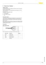
Electronics - Modbus 8 Electronics - Modbus Voltage supply The operating voltage and the digital bus signal are routed via separate two-wire connection cables. Power the instrument via an energy-limited circuit (power max. 100 W) acc. to IEC 61010-1. Specifications of the voltage supply: Operating voltage –– 8 … 30 V DC • max. number of sensors –– 32 Connection cable The instrument is connected with standard two-wire, twisted cable suitable for RS 485. If electromagnetic interference is expected which is above the test values of EN 61326 for industrial areas, shielded cable should be used. Make...
Open the catalog to page 12All VEGA TECHNIQUE catalogs and technical brochures
 PRODUCT OVERVIEW
80 Pages
 VEGAPULS 42
2 Pages
 VEGAFLEX 86
2 Pages
 VEGAFLEX 83
2 Pages
 VEGAFLEX 81,83,86
28 Pages
 VEGAFLEX 82
2 Pages
 VEGAFLEX 82, 86
24 Pages
 VEGAFLEX 81
2 Pages
 VEGAFLEX 81, 83, 86
28 Pages
 Guided Wave Radar
3 Pages
 Radar IIoT
4 Pages
 Radar
Radar6 Pages
 VEGAPULS 6X
20 Pages
 VEGAPULS 6X
2 Pages
 VEGAPULS Air 42
2 Pages
 VEGAPULS Air 41
2 Pages
 VEGAPULS Air 23
2 Pages
 VEGAPULS WL 61
2 Pages
 VEGAPULS WL S 61
2 Pages
 VEGAPULS SR 68
2 Pages
 VEGAPULS 69
2 Pages
 VEGAPULS 68
2 Pages
 VEGAPULS 67
2 Pages
 VEGAPULS 66
2 Pages
 VEGAPULS 65
2 Pages
 VEGAPULS 64
2 Pages
 VEGAPULS 63
2 Pages
 VEGAPULS 62
2 Pages
 VEGAPULS 61
2 Pages
 VEGAPULS 31
3 Pages
 VEGAPULS 21
2 Pages
 VEGAPULS 11
3 Pages
 VEGAPULS C 23
2 Pages
 VEGAPULS C 22
2 Pages
 VEGAPULS C 11
2 Pages
 VEGAPULS C 21
2 Pages
 WEIGHTRAC 31
2 Pages
 Hydrostatic VEGABAR, VEGAWELL
12 Pages
 Microwave barrier VEGAMIP
12 Pages


Archived catalogs
 Radar VEGAPULS
22 Pages


- Display module
- Automation software solution
- VEGA pressure transmitter
- VEGA level switch
- VEGA analog pressure transmitter
- VEGA liquid level switch
- VEGA level sensor
- Color display panel
- VEGA liquid level sensor
- VEGA waterproof pressure transmitter
- VEGA membrane pressure transmitter
- VEGA stainless steel pressure transmitter
- Interface software
- VEGA relative pressure transmitter
- VEGA analog level sensor
- Backlit display panel
- VEGA digital pressure transmitter
- Transceiver module
- VEGA stainless steel level switch
- VEGA gas pressure transmitter