- Products
- Catalogs
- News & Trends
- Exhibitions
V210CS - Hydraulic Unscrewing Device 210 bar
1 /12Pages

V210CS - Hydraulic Unscrewing Device 210 bar
1 /12Pages
Catalog excerpts

Hydraulic Unscrewing Device 210 bar Sistema oleodinamico per svitamenti 210 bar Cat.V210CS.2012.00.GB+IT
Open the catalog to page 1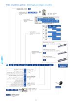
Order compilation symbols - Simbologia per redigere un ordine Cylinder MODEL V210CS Modello cilindro V210CS Cylinder BORE (ØX) ALESAGGIO cilindro - P. S4 ØX = Bore Alesaggio ØY = Rod Stelo Module - Modulo Rack MODULE MODULO cremagliera - P. S4 Pressure angle 20° - Angolo di pressione 20° ØX Rack LENGTH LUNGHEZZA cremagliera - P. S5 ONE RACK version (LEFT) Versione UNA CREMAGLIERA (SINISTRA) A ONE RACK version (RIGHT) Clamping & Rack Fissaggio e cremagliera - P. S6-7 Versione UNA CREMAGLIERA (DESTRA) BSP Thread - Filetto BSP NPT Thread - Filetto NPT Manifold with o-rings - Integrati con o-rings...
Open the catalog to page 2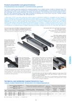
Product presentation and general features Presentazione del prodotto e caratteristiche generali The V210CS cylinders have been designed for actuating threaded cores on plastic injection moulds by integrated racks. The advantage of this solution is the compactness in overall dimensions, the standardization of all components with consequent price advantage and the specific application field design and accessories. The unscrewing device can be provided of one or two racks with customized length, a wide range of modules for actuating one or more cores in one time. Cylinder available bores 32, 40...
Open the catalog to page 3
Choice of BORE and rack MODULE Determinazione di ALESAGGIO e MODULO cremagliera Table PUSH and PULL FORCES in daN (1 daN = 1 Kgf) Tabella FORZE in SPINTA e TIRO in daN (1 daN = 1 Kgf) 8 MPa 80 bar-1160 PSI Push Pull Example of order code: Esempio di codice ordine: RACK max. LOAD* Table in kg - Tabella CARICO max. CREMAGLIERA* in kg Max. rack total load Max. rack single tooth load Carico max. su singolo dente Rack pressure angle 20° Angolo di pressione cremagliera 20° * NOTES: For a correct unscrewing device dimensioning, in addition to the mould design necessities, the following elements must...
Open the catalog to page 4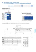
Choice of cylinder STROKE and RACK LENGTH Determinazione della CORSA del cilindro e della LUNGHEZZA della CREMAGLIERA. Example of order code: Esempio di codice ordine: RACK LENGTH Table in mm Tabella LUNGHEZZE CREMAGLIERA in mm Rack length Lunghezza cremagliera STANDARD STROKES Table in mm Tabella CORSE STANDARD in mm 32 40 50 Note: Stroke tolerance: -0/+0,5 mm Nota: Tolleranza sulla corsa: -0/+0,5 mm Limit measure for gear correct placement - Misure limite per il corretto posizionamento dei pignoni #: Stroke regulation screw. Regulation field ±2 mm - Vite di regolazione fine della corsa. Campo...
Open the catalog to page 5
Choice of RACK VERSION - Determinazione del TIPO DI CREMAGLIERA Example of order code: Esempio di codice ordine: ONE RACK version (LEFT) - Position M, R, E Versione UNA CREMAGLIERA (SINISTRA) - Posizione M, R, E ONE RACK version (RIGHT) - Position H, R, E Versione UNA CREMAGLIERA (DESTRA) - Posizione H, R, E NOTE: The position of rack, left or right, is defined by specifying the oil delivery side at P. S8. NOTA: La posizione della cremagliera, sinistra o destra, viene definita specificando la posizione degli orifizi a P. S8. NOTE: For dimensions where no tolerance is indicated, refer to DIN norm...
Open the catalog to page 6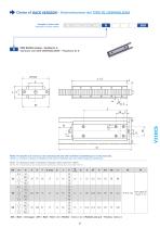
Choice of RACK VERSION - Determinazione del TIPO DI CREMAGLIERA Example of order code: Esempio di codice ordine: TWO RACKS version - Position R, E Versione con DUE CREMAGLIERE - Posizione R, E NOTE: The double rack version can be manufactured only with oil delivery manifold type or in the back side. NOTA: La versione a doppia cremagliera può essere realizzata solo con orifizi integrati o posteriori. NOTE: For dimensions where no tolerance is indicated, refer to DIN norm 7168-m NOTA: Per le dimensioni senza indicazione di tolleranza, riferirsi alla norma DIN 7168-m ØX = Bore - Alesaggio \ ØY =...
Open the catalog to page 7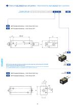
Choice of OIL PORTS type and position - Determinazione degli ORIFIZI tipo e posizione Example of order code: Esempio di codice ordine: BSP Threaded Oil Delivery - Orifizi filettati BSP (Gas) NPT Threaded Oil Delivery - Orifizi filettati NPT LEFT SINISTRA NOTE: Left or right side oil delivery available only with single rack; with left side OIL DELIVERY the rack will be on the right and vice versa. NOTA: L’alimentazione destra o sinistra sono disponibili solo per la versione ad una cremagliera; con ALIMENTAZIONE sinistra la cremagliera sarà a destra e viceversa. BSP Threaded Oil Delivery - Orifizi...
Open the catalog to page 8
Choice of OIL PORTS type and position - Determinazione degli ORIFIZI tipo e posizione Example of order code: Esempio di codice ordine: Manifold oil delivery - Orifizi integrati con O-Rings BOTTOM INFERIORE NOTES: FOR MANIFOLD OIL DELIVERY: Max. bore of the oil delivery hole in the mold: 4,5 mm for cylinder bore 32 to 50; 6 mm for other cyl. bore. Max. eccentricity 0,5 mm FKM O-Rings are included. NOTE: PER ORIFIZI CON O-RINGS: Diametro max. del foro di alimentazione da eseguire nello stampo: 4,5 mm per alesaggio cilindro da 32 a 50; 6 mm. Per gli altri. Eccentricità max. 0,5 mm. Gli O-Ring in...
Open the catalog to page 9
Choice of Cylinder VERSION - Determinazione della VERSIONE del cilindro Example of order code: Esempio di codice ordine: DESCRIPTION - DESCRIZIONE Cylinder WITH MAGNETIC PRESET (switches not included) Cilindro CON PREDISPOSIZIONE MAGNETICA (sensori non inclusi) Cylinder WITHOUT magnetic preset. Cilindro SENZA predisposizione magnetica. MAGNETIC SWITCHES (ONLY FOR “M” VERSION; usually two for cylinder) SENSORI MAGNETICI di fine corsa (SOLO PER VERSIONE “M”; solitamente due ogni cilindro) Order code: Codice d’ordine: Wire Colour Colore Conduttori Brown Marrone = +24V DC Blue Blu = 0V DC Black Nero...
Open the catalog to page 10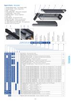
Cylinder bore Alesaggio cilindro Article Code Codice Articolo Ports position Posizione Additional set code Indicazione d’assieme Spare Parts - Ricambi 1. Joining bracket screw - Vite fissaggio staffa 2. Joining bracket - Staffa collegamento 3. Rack - Cremagliera 4. Rack guiding slide - Slitta guida cremagliera 5. Cylinder body - Corpo cilindro 6. Magnetic Switch - Sensore magnetico 7. Rod - Stelo 8. Rod seals kit - Kit guarnizioni stelo 9. Piston with seals - Pistone con guarnizioni 10. Piston seals kit - Kit guarnizioni pistone 11. Stroke adjust screw with seals - Vite regolazione fine della...
Open the catalog to page 11All VEGA SRL catalogs and technical brochures
 VS 450CM - YES
14 Pages
 V270CG
18 Pages
 V215CD
24 Pages
 V450 CP
36 Pages


- Double-acting cylinder
- Hydraulic cylinder
- Compact cylinder
- Industrial cylinder
- Standard cylinder
- Aluminum alloy cylinder
- ISO cylinder
- Stainless steel cylinder
- Steel cylinder
- Precision cylinder
- Cylinder with piston rod
- Tie-rod cylinder
- Micro cylinder
- Heavy load cylinder
- High-speed cylinder
- Block cylinder
- Integrated cylinder
- Small cylinder
- Alloy cylinder