- Catalogs
- Vectron International
- CD-700 A Quartz Stabilized PLL
CD-700 A Quartz Stabilized PLL
1 /20Pages

CD-700 A Quartz Stabilized PLL
1 /20Pages
Catalog excerpts

A Phase-Locked Loop ASIC ' ..with a Quartz Stabilized VCXO THREE APPLICATIONSj£^^y^ CLOCK RECOVERY AND DATA RETIMING CLOCK SMOOTHING Helping Customers Innovate, Improve & Grow
Open the catalog to page 1
Flexible Modular Solution A Quartz Stabilized PLL I t ’s a phase-locked loop ASIC with a quartz stabilized VCXO! Hermetic Seam Seal 16 Pad Leadless Chip Carrier It will : • Reduce: design time component count board space Castallations For Optimum board adhesion • Improve: jitter performance reliability It perf o rm s : • Clock Recovery & Data Retiming • Frequency Translation • Clock Smoothing • Clock Switching 2 In applications up to 65.536 Mb/s: • ATM, SONET/SDH, DWDM • xDSL, Network Communications • Digital Audio/Video, PBX Systems Vectron International 166 Glover Avenue, Norwalk, CT 06856-5160...
Open the catalog to page 2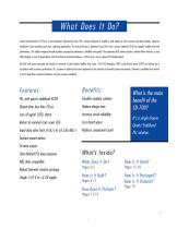
What Does It Do? Vectron International's CD-700 is a user-configured, phase-locked loop (PLL) solution designed to simplify a wide variety of clock recovery and data retiming, frequency translation, clock smoothing and clock switching applications. The device features a phase-lock loop ASIC with a quartz stabilized VCXO for superior stability and jitter performance. This highly integrated module provides unsurpassed performance, reliability and quality. The proprietary ASIC device includes a refined Phase Detector, a Loop Filter Op-Amp, a Loss of Signal Alarm with Clock Return to Nominal feature,...
Open the catalog to page 3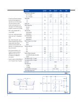
Output Frequency (ording option) 1,2 Out 1, 5.0 V option and input clock recovery applications, the output clock must run at two times the input Out 1, 3.3 V Option 1. For input RZ data, Manchester encoded data, Supply Voltage 3 +5.0 +3.3 Supply Current correctly. Since the output clock has a max- rate to ensure that the input is clocked Output Transition Times: imum frequency of 65.536 MHz, these inputs are limited to a maximum rate of 32.768 MHz. 2. OUT2 is a binary submultiple of OUT1, or it may be disabled. Input Logic Levels: Output Logic High 4 3. A 0.01uF and 0.1 parallel capacitor should...
Open the catalog to page 4
Negative input terminal to internal operational amplifier. Output signal produced by phase detector. Output terminal of internal operational amplifier. With LOSIN set to a logic high, the external input to the VCXO (VC) is disabled and the VCXO returns to it’s nominal center frequency. With LOSIN set to logic low, the external input to the VCXO is enabled. The LOSIN input has an internal pull-down resistor. Input data stream to phase detector (TLL switching thresholds). Input clock signal to phase detector (TTL switching thresholds). Circuit and cover ground. Loss of signal indicator is set to...
Open the catalog to page 5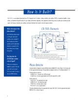
The CD-700 is a uset-configuted phase-locked loop (PLL) integrated circuit. It includes a voltage controlled crystal oscillator (VCXO), an operational amplifier, a phase detector, and additional integrated functions for use in digital synchronization applications. These applications include timing recovery and data pulse restoration for data signals, clock frequency translation and smoothing, synchronous distributed clock networks, and clock frequency synthesis. Phase Wed A : OrfpiJ QGSigrd FTafcdioiil Ic Mafac*PI:afleEnm ->LOS:L03KCampliHH'J, OiJpd Kgh dfsr25d Qisd((^clss|pi<£Jwlh noInptf Tiamliors...
Open the catalog to page 6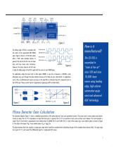
The falling edge of RCLK is coincident with the center of the regenerated NRZ RDATA pulse. Figure 6 shows a 1010 data stream with a 100% data transition density. In general, this will not be the case and input data will have fewer data transitions. However, the phase detector will still seek to align the falling edge of the RCLK signal with the center of each RDATA pulse. For applications where the input clock or data signal, DATAIN, is very low in frequency (<200kHz), clock information may pass through the phase detector because of its finite low pass characteristic. In applications such as...
Open the catalog to page 7
Phase Detector Gain = [VDD/2π] * [2/3] * D = 0.53 * D for 5 Volt and 0.35 * D for 3.3 Volt Supply Where D = input data transition density. For example D = 1 for 100% transition density (e.g., clock signal) and D = 0.5 for 50% transition density (e.g., balanced NRZ data). L O S and LOSIN The LOS circuit provides an output alarm flag when the DATAIN input signal is lost. The LOS output is set “logic high” after 256 consecutive CLKIN periods with no DATAIN transitions. This signal can then be used to either flag external alarm circuits and/or drive the CD-700’s LOSIN circuit. When the LOSIN input...
Open the catalog to page 8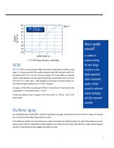
CD-700 VCXO Frequency Deviation vs. Control Voltage In addition to extensive testing, The CD-700's VCXO is a varactor-tuned crystal oscillator which produces an output frequency controlled by a control voltage, Vc. The tracking range of the VCXO is specified as absolute pull range (APR) when ordered. An APR of ±50 ppm guarantees that the CD-700 can track an input source frequency with ±50 ppm stability over all operating highly engineered, conditions, including temperature, time, power supply and load variations. A typical frequency versus Vc curve for the robust components; VCXO in the CD-700...
Open the catalog to page 9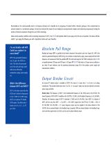
Mass-loading on the crystal generally results in a frequency decrease and is typically due to out-gassing of material within a hermetic package or from contamination by external material in a non-hermetic package. Vectron has minimized the impact of mass loading by ensuring hermetic integrity and minimizing out-gassing by limiting the number of internal components through the use of ASIC technology. Under normal operating conditions with an operating temperature of 40°C, the CD-700 will typically exhibit 2 ppm aging in the first year of operation. The device will then exhibit 1 ppm aging the...
Open the catalog to page 10
Handling Pre c a u t i o n s Although protection circuitry has been designed into this device, proper precautions should be taken to avoid exposure to electrostatic discharge (ESD) during handling and mounting. Vectron employs a Human Body Model (HBM) and a Charged Device Model (CDM) for ESD susceptibility testing and protection design evaluation. ESD voltage thresholds are dependent on the circuit parameters used to define the mode. very robust product MODEL Charged Device Human Body manufacturing line. It is packaged in a 16-pad ceramic with a seam-welded step lid, hermetically sealed for long...
Open the catalog to page 11All Vectron International catalogs and technical brochures
 PX-340
4 Pages
 PX-422
6 Pages
 M55310/16
4 Pages
 M55310/21
5 Pages
 M55310/30
6 Pages
 Timing Module Brochure
5 Pages
 OX-171 Holdover Oscillators
6 Pages
 VCC1 Crystal Oscillator (XO)
10 Pages
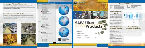 SAW Filter Products
2 Pages
 Military Products
9 Pages
 VXA7 Standard Crystal
2 Pages


Archived catalogs
 FX-702 Frequency Translation
7 Pages
 2009 catalog
8 Pages
 SAW Product Brochure
8 Pages


