- Catalogs
- VAT Vakuumventile AG
- HV gate valve
HV gate valve
1 /8Pages

HV gate valve
1 /8Pages
Catalog excerpts
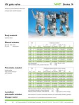
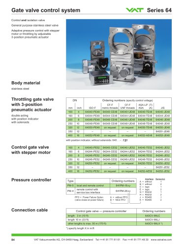
General purpose stainless steel valve Compact and variable actuator Body material stainless steel Manual actuator DN 63 - 350: lever DN 400: handwheel Ordering numbers ISO-F 14036-PE06 CF-F CF-F metric threads UNF threads 14036-CE06 with handwheel: 140 . . - . E01 (DN 63 - 350) with handwheel, with position indicator: 140 . . - . E08 Pneumatic actuator double acting with position indicator with solenoid Ordering numbers (specify control voltage) ISO-F CF-F CF-F metric threads UNF threads Stepper motor without position indicator, without solenoid: 140 . . - . E14 with position indicator, without solenoid: 140 . . - . E24 without position indicator, with solenoid: 140 . . - . E34 (specify control voltage) See series 64: 3-position pneumatic actuator with intermediate throttling position See series 64: for conductance and pressure control
Open the catalog to page 1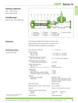
Sealing materials Gate: Feedthrough FKM (VITON) / rotary feedthrough 1 valve gate 2 ball guidance 3 leaf spring 4 ball pairs 5 detents 6 crank bolt valve seat side 7 gate seal 8 actuator shaft 9 counter plate Six actuator possibilities (three positions on either side) Rotary feedthrough for high cycle life, low particle count Optimized VATLOCK configuration (see glossary) Technical data ≤ 2 / ≤ 1.2 bar in either direction ≤ 30 mbar 200 000 reduced cycle life Temperature 1) - Valve body - Manual actuator, position indicator - Pneumatic actuator, motor, solenoid Material - Valve body, valve gate...
Open the catalog to page 2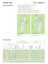
Actuator positions For optimum system design the actuator can be mounted: - on the A-side (valve seat side): standard - on the B-side: option (please indicate in your order) - in position 1 (standard for A- and B-side) - in position 2 (can be mounted by customer: for DN 63 restricted) - in position 3 (can be mounted by customer: for DN 63 restricted) a valve seat side a valve seat side Technical data closing or opening time compressed air pressure min. - max. overpressure manual handwheel molecular flow conductance standard flanges angle of rotation per stroke
Open the catalog to page 3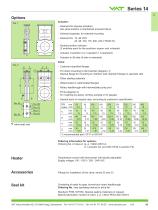
A Actuator: - Solenoid for impulse actuation: last valve position is maintained at power failure - Solenoid separate, for external mounting - Solenoid for 12, 48 V DC 24, 48, 100, 115, 200, 230 V 50/60 Hz - Double position indicator (2 switches each for the positions «open» and «closed») - Actuator in position 2 or 3 (position 1 is standard) - Actuator on B-side (A-side is standard) Valve: - Customer specified flanges - For direct mounting to flat chamber (diagram 1): Special flange for mounting to chamber wall, standard flange on opposite side - Other sealing materials - Watercooled or waterheated...
Open the catalog to page 4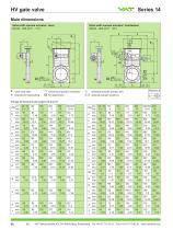
Main dimensions Valve with manual actuator: lever DN 63 - 350 (2 ½" - 14") valve seat side required for dismantling Valve with manual actuator: handwheel DN 63 - 400 (2 ½" - 16") mechanical position indication for attachment standard actuator position (A1) optional actuator positions Flange dimensions see pages 50 and 51 mm O inch O1 inch P inch Q inch
Open the catalog to page 5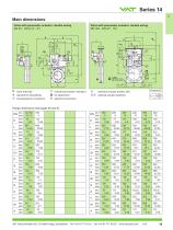
Main dimensions Valve with pneumatic actuator: double acting DN 63 - 100 (2 ½" - 4") valve seat side required for dismantling compressed air connection mechanical position indication for attachment electrical connection Valve with pneumatic actuator: double acting DN 160 - 400 (6" - 16") standard actuator position (A1) optional actuator positions Flange dimensions see pages 50 and 51 mm
Open the catalog to page 6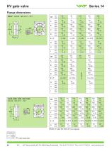
a valve seat side
Open the catalog to page 7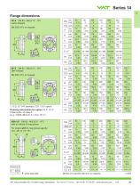
CF-F DN 63 - 250 (2 ½" - 10") metric threads H2 inch CF-F DN 63 - 250 (2 ½" - 10") UNF threads *) O.D. 12" VAT standard, O.D. 13 ¼" option Ordering information for option: O.D. 13 ¼" Ordering No. of valve-X (e. g. 14048-UE44-X, X = O.D. 13 1/4") ASA-LP DN 63 - 400 (2 ½" - 16") with or without O-ring groove For orders with O-ring groove specify: «A», «B» or «A + B» a valve seat side
Open the catalog to page 8All VAT Vakuumventile AG catalogs and technical brochures
 97.0 SERIES- MODULES
3 Pages
 271 series
2 Pages
 752 series
4 Pages
 590 series
4 Pages
 230 series
2 Pages
 191 series
8 Pages
 172 series
8 Pages
 HV angle valve
4 Pages
 Large door L-VAT
2 Pages
 Rectangular valve FlapVAT
2 Pages
 Atmospheric door L-VAT
4 Pages
 All-metal gate valve
8 Pages
 Large gate valves (V)
6 Pages
 HV gate valve with Bellows
8 Pages
 053
0534 Pages
 650
6509 Pages
 190
1906 Pages
 264
26410 Pages
 080 - Insertable gate valve
4 Pages
 Large Transfer valve
2 Pages
 540
5402 Pages
 284
2844 Pages
 243
2432 Pages
 220
2202 Pages
 Transfer valve
6 Pages
 022
0226 Pages
 640
64010 Pages
 612
6126 Pages
 091
0916 Pages
 010
0106 Pages
 VAT Catalogue 2012
234 Pages