640
1 /10Pages

640
1 /10Pages
Catalog excerpts

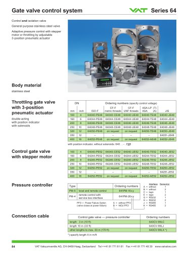
Gate valve control system Throttling gate valve pneumatic actuator double acting with position indicator with solenoids with position indicator, without solenoids: 640 . . -. E28 Control gate valve with stepper motor Pressure controller Connection cable
Open the catalog to page 1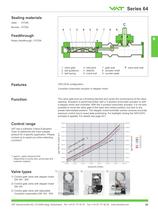
Sealing materials Gate: VITON Bonnet: VITON Feedth rough Rotary feedthrough / VITON V valve seat side VATLOCK configuration 3-position pneumatic actuator or stepper motor The valve gate acts as a throttling element and varies the conductance of the valve opening. Actuation is performed either with a 3-position pneumatic actuator or with a stepper motor and controller. With the 3-position pneumatic actuator, it is not only possible to move the valve gate to the open and closed position, but also to any preset intermediate position. The stepper motor/controller version ensures accurate pressure...
Open the catalog to page 2
Gate valve control system Technical data Maximum values: depending on operating conditions and sealing materials Leak rate: body, valve seat Pressure range Differential pressure - During opening / closing Cycles until first service - Valve body - Pneumatic actuator, motor - Position indicator - Valve body, gate Mounting position Valve position Connections actuator - Position indicator: contact rating - Stepper motor horizontal only (vertical mounting position: see «Options») compressed air (see table below)
Open the catalog to page 3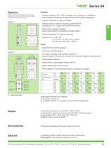
Certain options are not available for some nominal diameters or cannot be combined. Moreover, options can affect the general technical data. V valve seat side - Actuator rotated by 90° /180° to position 2 or 3 (position 1 is standard): see dimensional drawings on pages 88 and 89 for optimum adaptation - Actuator on B-side (A-side is standard) - Stepper motor for vertical mounting position DN 400 (closing time 15 s, cycles until first service 50000) - Solenoids for impulse actuation: actual valve position is maintained at power failure - Solenoid separate, for external mounting - Customer specified...
Open the catalog to page 4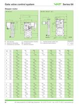
Gate valve control system Stepper motor V valve seat side ^ mechanical position indication © standard actuator position (A1) * required for dismantling □ for attachment ©® optional actuator positions © compressed air connection © electrical connection
Open the catalog to page 5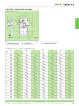
V valve seat side ^ mechanical position indication © standard actuator position (A1) * required for dismantling □ for attachment © ® optional actuator positions © compressed air connection © electrical connection 11 L + W, DN 100: without pneumatic connection 6 mm shorter
Open the catalog to page 6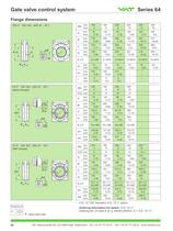
Gate valve control system Flange dimensions metric threads Ordering information for option: O.D. 'WW V valve seat side
Open the catalog to page 7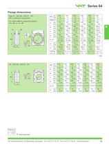
Flange dimensions with or without O-ring groove For orders with O-ring groove specify: V valve seat side
Open the catalog to page 8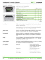
Gate valve control system Pressure controller Pressure control Position control Local operation Remote operation Logic interface PM-5: Version for local and remote control PM-4: Version for remote control The PM-4 / PM-5 controllers ensure fast and accurate pressure control. The LEARN function, being performed only once during system set-up, automatically determines all relevant system parameters. During pressure control the pressure controller continuously adapts to the process conditions (gas type, gas flow). No parameter inputs are necessary. The PM-4 / PM-5 controllers are provided with a...
Open the catalog to page 9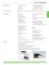
Digital inputs Digital outputs opening and closing of valve valve position open and closed Power Failure Option This function is available as an option. It automatically closes the valve at power Technical data Mains voltage Power required Ambient temperature Pressure control accuracy Position control Pressure sensor - Sensor input voltage - Sensor input - Sensor power supply Power Failure Option (PFO) - Akku type - Minimum charge time Inputs (interface option) Outputs (interface option) Weight: without PFO/with PFO 0.1 % of the sensor full scale range *) total for both sensors with 2-sensor...
Open the catalog to page 10All VAT Vakuumventile AG catalogs and technical brochures
 97.0 SERIES- MODULES
3 Pages
 271 series
2 Pages
 752 series
4 Pages
 590 series
4 Pages
 230 series
2 Pages
 191 series
8 Pages
 172 series
8 Pages
 HV angle valve
4 Pages
 Large door L-VAT
2 Pages
 Rectangular valve FlapVAT
2 Pages
 Atmospheric door L-VAT
4 Pages
 All-metal gate valve
8 Pages
 Large gate valves (V)
6 Pages
 HV gate valve
8 Pages
 HV gate valve with Bellows
8 Pages
 053
0534 Pages
 650
6509 Pages
 190
1906 Pages
 264
26410 Pages
 080 - Insertable gate valve
4 Pages
 Large Transfer valve
2 Pages
 540
5402 Pages
 284
2844 Pages
 243
2432 Pages
 220
2202 Pages
 Transfer valve
6 Pages
 022
0226 Pages
 612
6126 Pages
 091
0916 Pages
 010
0106 Pages
 VAT Catalogue 2012
234 Pages


- ERLO fitting
- ERLO manual valve
- ERLO control valve
- ERLO stainless steel valve
- ERLO pneumatic valve
- Pneumatic fitting
- ERLO solenoid valve
- Metal fitting
- Regulating valve
- Flange valve
- On/off valve
- Stainless fitting
- ERLO lever valve
- Electric valve
- Elbow fitting
- ISO valve
- Gas valve
- Valve with handwheel
- ERLO pneumatically-operated valve