- Catalogs
- VAT Vakuumventile AG
- 230 series

230 series

230 series
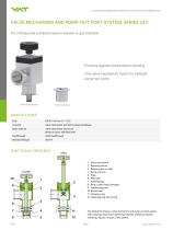
The Valve Mechanism and Pump-out Port System, Series 23.0, is designed to prevent unintentional opening and can be used with multiple pump-out ports. It features a self-locking handwheel actuator and is constructed from aluminum for the valve mechanism and stainless steel for the pump-out port. The system is compatible with ISO-KF standard flanges and is suitable for infrequently pumped vacuum vessels or gas isolation.
Components
1. Valve mechanism
2. Retaining device
3. Retaining pin on shaft
4. Pump-out port
5. Plate
6. Plate seal
7. Isolating plug
8. Plug-in shaft head / hexagon
9. Feedthrough seal
10. Bonnet seal
11. Clamping ring
12. Centering ring with O-ring
Technical Specifications
- Size: DN 16 – 40 mm (⅝" – 1½")
- Leak rate: 1 · 10-8 mbar ls-1 to < 1 · 10-9 mbar ls-1
- Pressure range: 1 · 10-8 mbar to 1 bar (abs)
- Temperature: Valve body ≤ 150 °C, Handwheel ≤ 50 °C
- Material: Valve body (EN AW-6060), Shaft and Plate (AISI 304)
- Seal: FKM (Viton®) for bonnet, feedthrough, and plate
- Mounting position: Any
- Stroke: DN 16, 25 (75 mm), DN 40 (107 mm)
- Unobstructed flow diameter: DN 16 (2.5 mm), DN 25 (8.0 mm), DN 40 (18.0 mm)
- Weight: DN 16 (0.35 kg), DN 25 (1 kg), DN 40 (1.2 kg)
Ordering Information
Valve mechanisms and pump-out ports are available in sizes DN 16, 25, and 40 with specific ordering numbers for each size.
Accessories
Flange connections for installation are available in series 31.
Catalog excerpts
VALVE MECHANISM AND PUMP-OUT PORT SYSTEM, SERIES 23.0 VALVE MECHANISM AND PUMP-OUT PORT SYSTEM, SERIES 23.0 For infrequently pumped vacuum vessels or gas isolation. Protects against unintentional opening One valve mechanism (lock) for multiple pump-out ports Valve mechanism Pump-out port MAIN FEATURES Size valve mechanism with self-locking handwheel Body material valve mechanism: aluminum pump-out port: stainless steel shaft feedthrough Standard flanges FUNCTIONAL PRINCIPLE 1 Valve mechanism 2 Retaining device 3 Retaining pin on shaft 4 Pump-out port 5 Plate 6 Plate seal 7 Isolating plug 8 Plug-in shaft head / hexagon 9 Feedthrough seal 10 Bonnet seal 11 Clamping ring 12 Centering ring with O-ring The illustration shows a valve mechanism and pump-out port system with clamping ring (11) and centering ring (12). Clamping ring and centering ring are not part of the system. 260
Open the catalog to page 1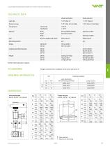
VALVE MECHANISM AND PUMP-OUT PORT SYSTEM, SERIES 23.0 ORDERING INFORMATIONDIMENSIONS Valve mechanism DN 16 - 40 (%" - 1/") ISO-KF V Valve seat side # Required for dismantling
Open the catalog to page 2All VAT Vakuumventile AG catalogs and technical brochures
 97.0 SERIES- MODULES
3 Pages
 271 series
2 Pages
 752 series
4 Pages
 590 series
4 Pages
 191 series
8 Pages
 172 series
8 Pages
 HV angle valve
4 Pages
 Large door L-VAT
2 Pages
 Rectangular valve FlapVAT
2 Pages
 Atmospheric door L-VAT
4 Pages
 All-metal gate valve
8 Pages
 Large gate valves (V)
6 Pages
 HV gate valve
8 Pages
 HV gate valve with Bellows
8 Pages
 053
0534 Pages
 650
6509 Pages
 190
1906 Pages
 264
26410 Pages
 080 - Insertable gate valve
4 Pages
 Large Transfer valve
2 Pages
 540
5402 Pages
 284
2844 Pages
 243
2432 Pages
 220
2202 Pages
 Transfer valve
6 Pages
 022
0226 Pages
 640
64010 Pages
 612
6126 Pages
 091
0916 Pages
 010
0106 Pages
 VAT Catalogue 2012
234 Pages