


- Company
- Products
- Catalogs
- News & Trends
- Exhibitions
Working Instructions & Maintenance

Working Instructions & Maintenance
Varvel speed reducers and variators are classified as machinery components and must be incorporated into machinery that complies with essential health and safety requirements. Proper operation and servicing require adherence to the manual's instructions.
Gearboxes and variators may heat up during operation. Handling, including transport, storage, assembly, and maintenance, must be performed by trained personnel following the manual and safety regulations.
Designed for industrial applications, these gearboxes and variators comply with applicable standards and regulations. Performance data is available on the unit's nameplate and related documentation.
Inspect goods for damage upon receipt. For long-term storage, keep units in a dry, dust-free environment and apply anti-oxidants to shafts and machined surfaces. Replace oil seals for storage over a year.
Dispose of scrapped components at authorized centers, deliver drained oils to Exhausted Oil Centres, and recycle packaging materials in line with ISO14001.
The document provides layouts for various gearbox types, detailing components and assembly versions, including specifications for motor kits, coupling types, and torque values.
Installation instructions cover tolerances, precautions, groundwork, and specific components like pinions and couplings to ensure optimal performance and safety.
Starting procedures are outlined for different series, ensuring correct operation from the outset.
Regular inspections and maintenance are crucial for optimal performance, with specified intervals and services to prevent malfunctioning.
Guidance is provided for addressing major malfunctions and accessing customer service support.
Recommended lubricant types and quantities are specified to ensure proper operation and longevity of the gearboxes.
The document includes information on compliance with Directive 2014/34/UE (ATEX) and provides a Declaration of Conformity.
The document outlines components and assembly instructions for different gearbox series, with detailed parts lists for Series VR and VS.
Installation tolerances are specified according to DIN 748 standards, with precautions to prevent vibrations and damage.
Regular inspections and maintenance schedules are outlined, including oil seal checks and lubricant replacement intervals.
Synthetic long-life oils are recommended for safe operation within specified temperature ranges.
Gearboxes are designed according to Directive 2014/34/EU for use in potentially explosive atmospheres, with specific construction and safety factors.
Ensure proper installation and maintenance, use recommended lubricants, and adhere to specified service intervals. Follow additional safety instructions for ATEX environments.
This document outlines methodologies related to non-electrical devices for explosive atmospheres as per EN ISO 80079-36:2016 and EN ISO 80079-37:2016.
Temperature requirements emphasize proper ventilation to ensure temperatures do not exceed 55°C.
All electric motors and components must be ATEX approved, with regular cleaning and proper earthing required for safety.
VARVEL Series gearboxes conform to Group II, Category 2, suitable for areas with explosion risks.
The document explains classification of materials, zones, categories, and equipment protection levels for gas and dust environments.
Lists various gases and their corresponding temperature classes for safe operation.
Maintenance intervals are crucial for ensuring explosion-proof protection, with recommendations for regular dust removal and oil replacement.
Includes a specimen of the UE Declaration of Conformity, confirming compliance with Directive 2014/34/EU (ATEX).
Catalog excerpts

IUM - WORKING INSTRUCTIONS AND MAINTENANCE - ATEX MANUAL
Open the catalog to page 1
General Information - Safety Warnings - Product Layout General Information Varvel speed reducers and variators are not in the field of application of the Machinery Directive 2006/42/CE as considered “machinery components”. Guide of Machinery Directive - § 35 - decrees: "The Machinery Directive does not apply directly to machinery components, such as, for example, valves, hydraulic cylinders or gearboxes, that do not have a specific application as such but are intended to be incorporated into machinery, although the design and construction of such components must enable the complete machinery...
Open the catalog to page 2
Coupling “G” The flexible coupling “G” is supplied on the Series RD, RN, RO, RV, RP, RS, RT as standard input equipment. The bore version with keyway is supplied on demand. (A) - Gearbox half-coupling (B) - Spider (C) - Motor half-coupling Advantages Friction clamped coupling on motor shaft IEC/NEMA adapters and couplings fitted on already assembled gearbox Elimination of fretting corrosion between bore and key Zero backlash in gearbox/motor connection Angular allowed misalignment lower than 1° High torsional rigidity A Mt - Screw locking torque Mt1 - Transmissible torque with key...
Open the catalog to page 3
Series RC - 2 stages RC-2 The layout shows the general structure of a two-stage foot-mounted helical gearbox type FRC (sizes 05 to 30). Ask for part list of other sizes 40 to 60, flanged output, input solid shaft and four stage executions. Motor cover Pinion shaft Input hollow shaft Input hollow pinion shaft Output shaft
Open the catalog to page 4
Series RC - 3 stages RC-3 The layout shows the general structure of a two-stage foot-mounted helical gearbox type FRC (sizes 05 to 30). Ask for part list of other sizes 40 to 60, flanged output, input solid shaft and four stage executions. Output shaft Input hollow shaft, toothed Intermediate housing Input cover Input hollow shaft, stud
Open the catalog to page 5
Series RD - 2 stages RD-2 The layout shows the general structure of a two-stage foot-mounted helical gearbox type FRD. Ask for part list of flanged output and input solid shaft. Input cover Motor Flange
Open the catalog to page 6
Series RD - 3 stages RD-3 The layout shows the general structure of a three-stage foot-mounted helical gearbox type FRD. Ask for part list of flanged output and input solid shaft. Input cover Upper cover Motor flange Output shaft
Open the catalog to page 7
Series RG - 1 stage RG-1 The layout shows the general structure of a one-stage planetary gearbox type FRG. Ring gear body Motor flange Planet gear Needle bearing Input flange Planet shaft Planet carrier Clamp coupling Input shaft
Open the catalog to page 8
Series RG - 2 stages RG-2 The layout shows the general structure of a two-stage planetary gearbox type FRG. Ring gear body Motor flange Planet gear Needle bearing Input flange Planet shaft Planet carrier Planet gear Clamp coupling Needle bearing Planet shaft Input shaft Planet carrier
Open the catalog to page 9
RN-2 The layout shows the general structure of a two-stage parallel shaft gearbox type FRN with through hollow output shaft. Ask for part list of flanged output and input solid shaft. Input flange Input shaft Output shaft
Open the catalog to page 10
RN-3 The layout shows the general structure of a two-stage parallel shaft gearbox type FRN with through hollow output shaft. Ask for part list of flanged output and input solid shaft. Motor flange Input shaft Output shaft
Open the catalog to page 11
RO-2 The layout shows the general structure of a two-stage bevel/helical gearbox type FRO with through hollow output shaft. Ask for part list of flanged output and input solid shaft. Motor flange Input shaft Gleason pinion Output shaft Gleason gear
Open the catalog to page 12
RO-3 The layout shows the general structure of a three-stage bevel/helical gearbox type FRO with through hollow output shaft. Ask for part list of flanged output and input solid shaft. Motor flange Output shaft Input shaft
Open the catalog to page 13
RV-3 The layout shows the general structure of a three-stage bevel/helical gearbox type FRV with through hollow output shaft. Ask for part list of flanged output and input solid shaft. Motor flange Input shaft Output shaft
Open the catalog to page 14
Series RP and XA RP and XA The layout shows the general structure of a one-stage flange mounting helical gearbox type FRP and FXA . Output shaft Motor flange Flexible coupling
Open the catalog to page 15
RS The layout shows the general structure of a worm gearbox type FRS with through hollow output shaft and shaft mounting. The Series TA (helical / worm) are made of a helical one-stage gearbox XA mounted as input stage onto a standard worm box RS and the Series RS/RS (two stage worm) of two standard worm boxes RS and an appropriate combination kit. Side cover Motor flange Worm wheel
Open the catalog to page 16
RT The layout shows the general structure of a foot-mounted worm gearbox type FRT. The Series TA (helical / worm) are made of a helical one-stage gearbox XA mounted as input stage onto a standard worm box RT and the Series RT/RT (two stage worm) of two standard worm boxes RT and an appropriate combination kit. Side cover Motor flange Worm wheel
Open the catalog to page 17
TLI - TLE Torque Limiter Options TLI - TLE The layout shows the general structure of a built-in torque limiter type TLI incorporated inside a worm gearbox Series RS or RT and type TLE to fit inside a worm gearbox Series RS or RT. The TLI type is incorporated during the gearbox assembly, while the type TLE can be directly fitted into the hollow shaft of an already assembled standard gearboxes without any special tooling. Rear friction Rear washer Rear bush Bellville washer Setting torque hand wheel Front washer Belville washer Front friction Front protection Worm wheel Front bush Hollow output...
Open the catalog to page 18
Series VR VR The layout shows the general structure of a flange-mounted variator without gearbox type. Control hand wheel Control shaft lock Control shaft Seal plate Index scale Output shaft Friction ring carrier Cylindrical slide Friction ring Cone holder Bellows seal Output flange
Open the catalog to page 19
Series VS VS The layout shows the general structure of a flange-mounted variator without gearbox type. Output shaft Planet carrier Sliding bush Adjusting track Ball carrier External mobile track External fixed track Internal fixed track Internal mobile track Belville washer
Open the catalog to page 20All VARVEL catalogs and technical brochures
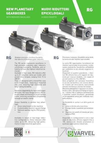 RG 2025
2 Pages
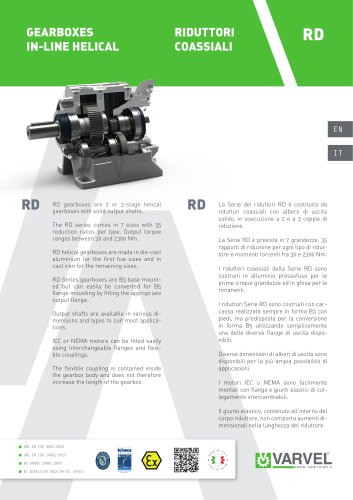 RD 2025
2 Pages
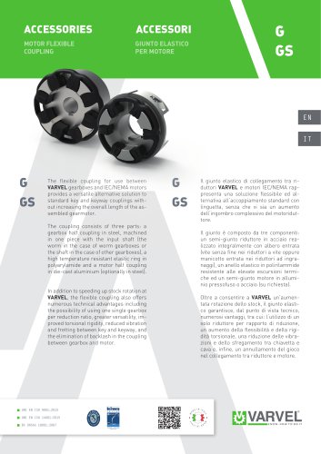 G/GS
G/GS2 Pages
 XA series
8 Pages
 RN series
92 Pages
 VS series
16 Pages
 VR catalogue
20 Pages
 RD catalogue
64 Pages
 RS/RT datasheet
2 Pages
 RG
RG2 Pages
 RO-RV
RO-RV96 Pages
 RN
RN92 Pages
 RD
RD60 Pages
 RS-RT
RS-RT72 Pages
 VR
VR20 Pages
 VS
VS16 Pages
 Product Range
8 Pages
 XA
XA8 Pages
 ATEX Manual
36 Pages
 Catalog RO2
64 Pages
 RC
RC44 Pages
 ISM-BSM
12 Pages
 Company Profile
28 Pages
 RG Catalogue
28 Pages
 ISM/BSM
2 Pages
 FRP680
2 Pages
 RO2
RO22 Pages
 RO/RV
RO/RV2 Pages


Archived catalogs
 ISM/BSM 2021
12 Pages
 Gearboxes for Servomotors
40 Pages
 RS/RT
RS/RT2 Pages
 G/GS series
4 Pages
- Planetary gearbox
- Coaxial gearhead
- Precision gearhead
- Right angle gearhead
- Solid-shaft gearhead
- Shaft shaft coupling
- Hollow-shaft gearhead
- Gear train gear reducer
- Gearbox for industrial applications
- Multi-stage gearhead
- Single-stage gearhead
- Shaft gearhead
- Helical gear gearhead
- Machines gearbox
- Dual-stage gearbox
- Low-backlash gearhead
- High-efficiency gearhead
- Electric motor gearhead
- Bevel gearhead